
Electric power compensation system with temperature control function, and using method thereof

A compensation system and electric power technology, which is applied in the direction of electrical components, substation/power distribution device casing, substation/switch layout details, etc., can solve the problem of large power consumption and achieve the effect of increasing stability and ensuring stability

Active Publication Date: 2021-06-01
山东程控电气有限公司
View PDF4 Cites 0 Cited by
  • Summary
  • Abstract
  • Description
  • Claims
  • Application Information

AI Technical Summary

Problems solved by technology

With the development of chip technology, the volume of the chip itself is getting smaller and smaller, but the power consumption is getting bigger and bigger, and the heat flux density is also greatly increased, and when other components in the system work, they will also To generate heat, simply using a cooling fan or a local chip water cooling device can no longer meet the temperature requirements of the chip quickly. The main reason is the interference of other internal high temperatures, so it is difficult to solve the problem of chip overload and overheating inside the system.

Method used


Image

  • Electric power compensation system with temperature control function, and using method thereof
  • Electric power compensation system with temperature control function, and using method thereof
  • Electric power compensation system with temperature control function, and using method thereof

Examples


Embodiment Construction

[0039] The implementation of the present application will be described in detail below with reference to the drawings and examples, so as to fully understand and implement the implementation process of how the present application uses technical means to solve technical problems and achieve technical effects.

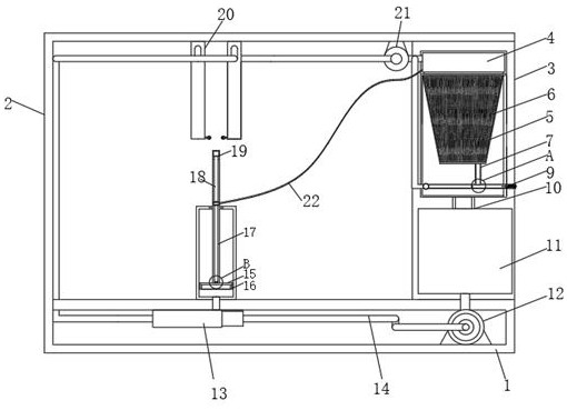
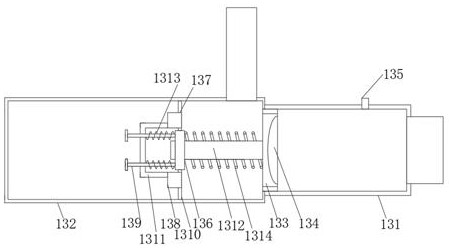
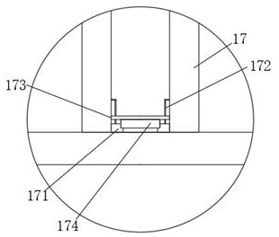
[0040] Such as Figure 1-8 As shown, the present invention provides a power compensation system with temperature control, including:

[0041] Box one 1 and box two 2, the right side of the inner cavity of box one 1 is provided with a frequency conversion pressurized water pump 12, the middle part of the inner wall top of box one 1 is fixedly connected with pressure shunt 13, the top of box one 1 and A primary cooling system is provided directly above the pressure splitter 13, and the primary cooling system communicates with the inner cavity of the pressure splitter 13, and the top of the inner wall of the box body 2 is provided with two connected contact condensers 20, a...


PUM


Abstract

The invention relates to the technical field of electric power compensation equipment, and concretely relates to an electric power compensation system with a temperature control function, and a using method thereof. The electric power compensation system comprises a first box body and a second box body, a frequency conversion pressurizing water pump is arranged on the right side of an inner cavity of the first box body, and a pressure flow divider is fixedly connected to the middle of the top of the inner wall of the first box body; a first-stage cooling system is arranged at the top of the first box body and located over the pressure flow divider, the first-stage cooling system is communicated with the inner cavity of the pressure flow divider, two communicated contact type condensers are correspondingly arranged at the top of the inner wall of the second box body, and a suction pump is arranged on the right side of the inner wall of the second box body; and the variable-frequency pressurizing water pump, the pressure flow divider and the suction pump are communicated through a connecting pipe. The invention provides a mode of intervening cooling of the chip in the system by adopting water pressure shunting, so that the cooling efficiency is improved, and the chip cannot be influenced by the temperature generated by other electrical components.

Description

technical field [0001] The invention relates to the technical field of aluminum rod processing, in particular to a power compensation system with temperature control and a use method thereof. Background technique [0002] The power compensation system (power reactive power compensation system) is an extremely common power equipment used in power distribution. The reactive power of the power system plays a very important role in voltage stability, but the loss of reactive power is relatively high during transmission. If the distance is too long, the loss may reach more than 50%, so it is not suitable for long-distance transmission. It is only suitable for hierarchical compensation and local balance. Therefore, reactive power compensation systems need to be arranged in each power consumption area. Camera → switch switched fixed capacitorStatic Var Compensator (SVC) → several different stages until today Static Var Generator SVG (STATCOM). [0003] During the operation of h...

Claims


Application Information

Patent Timeline
IPC IPC(8): H02B1/46H02B1/56H02B1/54H02B1/28
CPCH02B1/46H02B1/565H02B1/54H02B1/28
Inventor 裴方虚
Owner 山东程控电气有限公司
Learn More