MRAS speed estimation method based on single-neuron PID controller

A single neuron, speed estimation technology, applied in the control of electromechanical brakes, control systems, control generators, etc., can solve the problems of difficult parameter tuning, inability to accurately and quickly realize motor speed estimation, etc., to improve the observation accuracy and speed. Effect

Pending Publication Date: 2021-05-28
HARBIN UNIV OF SCI & TECH
View PDF0 Cites 0 Cited by
  • Summary
  • Abstract
  • Description
  • Claims
  • Application Information

AI Technical Summary

Problems solved by technology

However, in this method, the adaptive law is based on the conventional PID controller, the parameter tuning is difficult, and the motor speed estimation cannot be realized accurately and quickly.

Method used


Image

  • MRAS speed estimation method based on single-neuron PID controller
  • MRAS speed estimation method based on single-neuron PID controller
  • MRAS speed estimation method based on single-neuron PID controller

Examples


Embodiment Construction

[0038] In order to better understand the present invention, the present embodiment will be described in detail below in conjunction with the accompanying drawings.

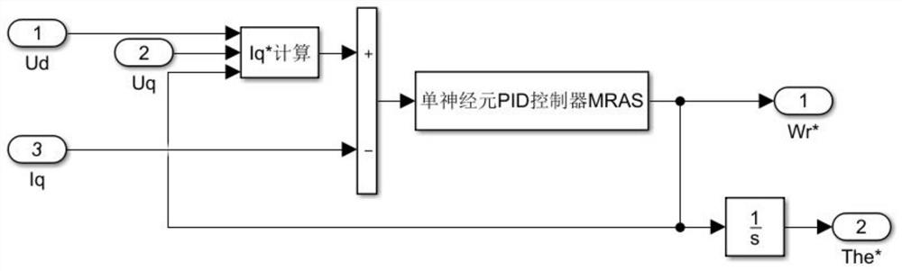
[0039] According to the mathematical model of the permanent magnet synchronous motor in the synchronous rotating coordinate system, the reference model and adjustable model based on the q-axis current MRAS are constructed when the id=0 vector control strategy is used, as shown in formula (1):

[0040]

[0041] where ω ω * are the actual and estimated rotor angular velocities, respectively; are the actual and estimated q-axis currents, respectively; u q is the q-axis voltage; R is the stator winding resistance; ψ r is the rotor flux linkage; L s is the inductance.

[0042] Defining the state generalized deviation is:

[0043] (1) The state error equation obtained by subtracting the two equations in the formula is shown in the formula (2): .

[0044]

[0045] In the formula,

[0046] Without loss o...


PUM


Abstract

The invention discloses an MRAS speed estimation method based on a single-neuron PID controller. The method is used for detecting the rotating speed of a permanent magnet synchronous motor when the permanent magnet synchronous motor runs without a speed sensor. According to the method, when the permanent magnet synchronous motor adopts id=0 control, on the basis of MRAS deduced based on q-axis current, a single-neuron PID controller is adopted to improve a conventional PID controller solve the problems that the conventional PID controller is difficult in parameter setting, cannot achieve online self-setting and the like. Simulation results show that the MRAS speed estimation method adopting the single-neuron PID controller can quickly and accurately realize estimation of the rotating speed of the permanent magnet synchronous motor, and provides theoretical basis and reference for practical application in the industry.

Description

technical field [0001] The invention relates to the field of permanent magnet synchronous motor control, in particular to an MRAS speed estimation method based on a single neuron PID controller. Background technique [0002] At present, in industrial control systems, it is more common to install mechanical speed sensors such as encoders or resolvers on the shaft of permanent magnet synchronous motors to obtain the speed and position signals of the rotor, but the installation of sensors will increase the cost of the entire system. The moment of inertia of the rotating shaft is increased, and the space size of the motor is increased. In addition, in harsh environments, the interface circuit between the digital signal processor and the sensor is susceptible to interference, and the measurement accuracy is easily affected. Therefore, in order to overcome the above problems brought by the use of mechanical sensors to the transmission system, the speed sensorless control technolo...

Claims


Application Information

Patent Timeline
IPC IPC(8): H02P21/18H02P21/00
CPCH02P21/0014H02P2207/05H02P21/18
Inventor 康尔良陈健
Owner HARBIN UNIV OF SCI & TECH
Why Eureka
Try Eureka