Taper milling cutter for worm machining

A technology of taper and milling cutter, which is applied in the direction of milling cutter, metal processing equipment, manufacturing tools, etc., can solve the problems of dull turning, low service life and low processing efficiency, and achieve the possibility of reducing burrs, simple tool structure and cutting efficiency high effect

Pending Publication Date: 2021-05-25
SUZHOU AHNO PRECISION CUTTING TECH CO LTD
View PDF0 Cites 1 Cited by
  • Summary
  • Abstract
  • Description
  • Claims
  • Application Information

AI Technical Summary

Problems solved by technology

Turning mostly uses high-speed steel or hard alloy forming turning tools and blades; high-speed steel forming turning tools have low cost and simple manufacturing process, but they are only suitable for low-speed turning, with low processing efficiency, poor tool durability, and low life. Due to the weakness of the CNC lathe when it rotates at a low speed, turning the worm or large-lead thread on the CNC lathe with a forming knife is prone to "stuck" and "knives" phenomena; the carbide forming turning tool has high processing efficiency and good cutting quality , but the tool life is still slightly insufficient
The worm milling cutters processed by CNC milling can be divided into sheet milling cutters or finger milling cutters. The tool life and cutting efficiency are high, but most worm milling cutters need to be processed with special tooling or machine tool clamping, which has poor versatility and low processing costs. high

Method used


Image

  • Taper milling cutter for worm machining
  • Taper milling cutter for worm machining
  • Taper milling cutter for worm machining

Examples


Embodiment Construction

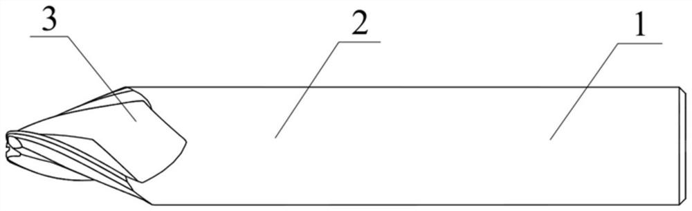
[0029] A tapered end mill for worm machining, such as figure 1 As shown, it includes a tool holding shank 1, a tapered cutting edge 3 and a transition neck 2. The transition neck 2 is used to connect the tool holding shank 1 and the cutting edge 3. The tool holding shank 1 is Cylindrical straight shank; the tool is mainly used for cutting carbon steel or alloy steel, the material of the milling cutter is 12% cobalt, hardness and fracture toughness K IC Higher ultra-fine-grained cemented carbide; the cutting edge 3 is tapered, with a single-side taper of 10° to 20°, and the diameter of the tapered cutting edge 3 is d 2 ;Diameter d of tool holder shank 1 1 is greater than or equal to the diameter d of the cutting edge portion 3 2 , the diameter d of the tool holding shank 1 1 The smallest even value obtained by converting the taper size δ and the taper overhang length l; the total length L of the tool is the sum of the lengths of the tool holding shank 1, the transition neck ...


PUM

PropertyMeasurementUnit
Radiusaaaaaaaaaa

Abstract

The invention provides a taper milling cutter for worm machining. The taper milling cutter is simple in structure, does not need a special tool or a machine tool for clamping and machining, and is high in universality and high in cutting efficiency. The tape milling cutter comprises a cutter clamping handle part, a taper-shaped cutting edge part and a transition neck part, wherein the transition neck part is used for connecting the cutter clamping handle part to the cutting edge part, the cutter clamping handle part is a cylindrical straight handle, a plurality of spirally-arranged cutting edges and chip grooves are arranged on the cutting edge part, chip-containing grooves are formed in the chip grooves and provided with groove bottom surfaces and cutter outlet surfaces; the cutting edges are formed by intersecting lines of the chip-containing grooves, the chip grooves and a tool entity part. In the cross section state, the multiple cutting edges are annularly distributed on the outer circumference of the center area of the cutting edge part in an equally-divided structure. Each cutting edge is composed of an end edge, a circumferential edge and a tool nose R angle used for connecting the end edge to the circumferential edge, each of the end edge and the circumferential edge is provided with a front tool surface and a straight rear tool surface, and each straight rear tool surface is composed of a plurality of straight-edge rear tool surfaces which are arranged in sequence to form corresponding rear angles with different angles.

Description

technical field [0001] The invention relates to the technical field of milling cutter structures, in particular to a tapered milling cutter for worm machining. Background technique [0002] Worm gear is a transmission structure used to transmit motion and power between two interlaced shafts. It has been widely used because of its advantages such as large transmission ratio, accurate and stable transmission, high mechanical efficiency, long service life and safe and reliable operation. In all kinds of modern mechanical devices. [0003] Worm gears and worms are equivalent to gears and racks in their mid-plane, and worms are similar in shape to screws, usually with one or several helical teeth, and their indexing surfaces can be cylindrical, conical or toroidal. The worm material is mainly carbon steel or alloy steel, such as 12CrNi3A, 18CrMnTi, 20CrMnTi, 20Cr, 20CrV, A6, 40, 45, 40Cr, 40CrNi and 42CrMo. [0004] At present, the methods of processing worms in China can be ro...

Claims


Application Information

Patent Timeline
IPC IPC(8): B23C5/10
CPCB23C5/10
Inventor 沈钰高伟建
Owner SUZHOU AHNO PRECISION CUTTING TECH CO LTD
Why Eureka
Try Eureka