
Contact piece and connector

A technology of contact parts and contact rings, applied in contact parts, welding/welding connections, connections, etc., can solve problems such as physical gaps, pollution from excessive usage, and difficult control

Pending Publication Date: 2021-05-18
GUIZHOU SPACE APPLIANCE CO LTD
View PDF2 Cites 0 Cited by
  • Summary
  • Abstract
  • Description
  • Claims
  • Application Information

AI Technical Summary

Problems solved by technology

In the prior art, the elastic socket contact often adopts the structure of protective tube, pin and contact ring. For example, the Chinese patent with publication number CN109149206A provides a miniaturized crown spring type socket assembly, including protective tube, The pin and the crown spring contact ring, the contact ring is installed in the protective tube, the pin is set on the rear end of the protective tube and the contact ring, the protective tube and the pin are assembled with an interference fit segment structure, the socket fits and the connection The base of the device is fixed by the transitional step structure in the stamping process, and the structure of a single thorn is used to realize the radial anti-rotation function of the socket fitting in the base. In this technology, the two parts of the protective tube and the pin are mechanically The interference fit is fixed together, the number of part structures is large, the structure and its assembly process are relatively complex, and due to the height and size limit of the jack contact, the height of the mating surface of the protective tube and the pin is generally not more than 1mm, so that there is a problem at the mating surface. The risk of physical gaps, in the process of welding and use, or the amount of organic solvents such as flux is large, or the process protection is improper, there is a risk of excess contamination, resulting in poor contact
The radial structural strength of the mating surface of the protective tube and the pin is also affected by the wall thickness and material of the protective tube. If it is subjected to radial mechanical stress during assembly or use, the matching structure may be loosened. Here, the contact point of the signal transmission channel Reduced, increased risk of excess contamination and poor signal transmission
[0003] The Chinese patent with the publication number CN210006971U provides a one-piece crown spring socket assembly, including the socket and the crown spring contact ring. The structure is designed with a circle of limit arc-shaped protrusions on the inner wall of the socket to carry out the contact ring The fixing of the socket fitting is fixed through the transition step structure of the stamping process, and the radial anti-rotation function of the socket fitting in the base is realized by processing the flattened surface on the inclined surface of the tail end of the socket. The structure cannot avoid the matching gap between the socket contact and the radial mating circle of the connector insulator, and liquids such as organic solvents are also likely to flow from the tail end of the connector to the butt end through this channel to cause pollution, and there is a greater impact on the orientation of the socket fitting. Products with high requirements for terminal connection (such as bent-insert printed board type), the effectiveness of cutting and positioning is insufficient
[0004] At the same time, the jack contact is an important part of the connector, and its structure and performance reliability are the key to determining the basic functions of the connector. In the prior art, there is a flow channel between the tail welding point and the butt end, and the welding process is difficult to control. It is even more difficult to realize automatic welding, which greatly restricts the processing, quality cost and production cycle of large-core connectors.

Method used


Image

  • Contact piece and connector
  • Contact piece and connector
  • Contact piece and connector

Examples


Embodiment 1

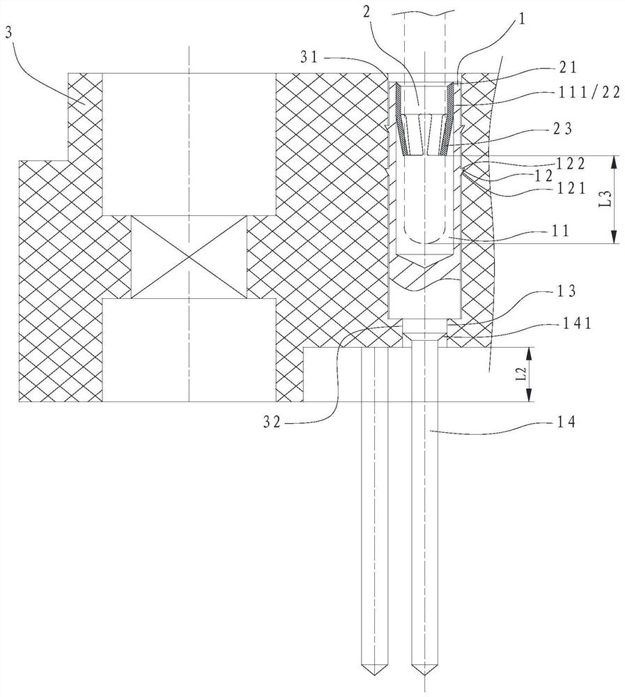
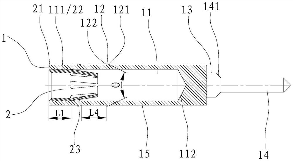
[0038] Such as figure 1 , figure 2As shown, a contact piece includes a body 1 and an elastic mechanism. The butt end of the body 1 is a socket of a standard diameter, and the socket is provided with a blind hole 11 for loading the elastic mechanism. The elastic mechanism is a spring claw 2, and Through the elastic interference fit of the outer circle 22 of the spring claw and the mouth 111 of the blind hole 11, the minimum interference fit of the circumference is 0.01mm, and the axial height L1 of the matching section is not less than 0.5mm, so as to ensure the outer circle of the spring claw 22 and the blind hole opening 111 to prevent the spring claw 2 from coming out under force when the connector is plugged and pulled out. The outer wall 15 of the body 1 is designed with double-circle struts 12 that are interference fit with the base 3, and the struts 12 form a complete and continuous whole around the outer wall 15, so that the two circles of struts are opposite to the o...

Embodiment 2

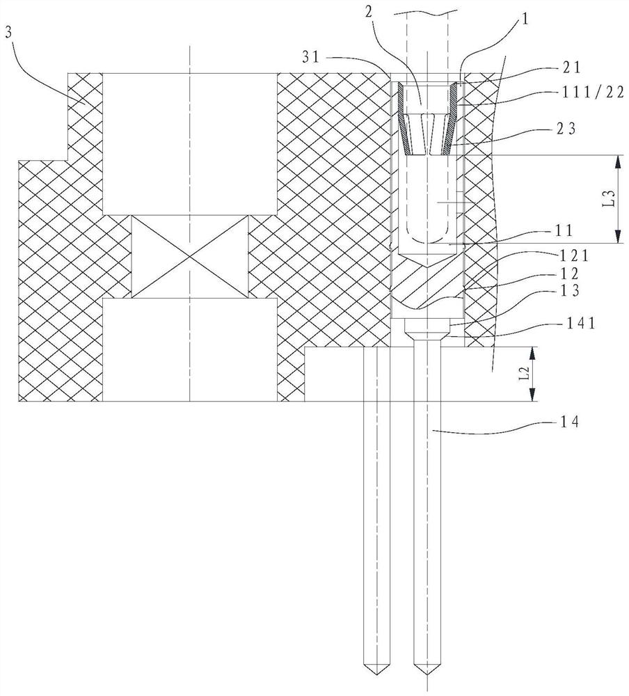
[0045] Such as image 3 , Figure 4 As shown, on the basis of the structure of Embodiment 1, the structure of the socket and the base 3 has the following changes:

[0046] A process hole 16 is added to the side wall of the bottom 112 of the blind hole 11, and the diameter of the process hole 16 cannot be less than φ0.3mm, so as to ensure the coating coverage and environmental resistance of the bottom 112 of the inner hole. At this time, the two circles of stabs 12 are located between the process hole 16 and the tail end of the insertion hole, and the tapered surface 121 of the stabs 12 is arranged on the side close to the butt end of the insertion hole. At this time, the inner hole 31 of the base 3 is a through-hole structure, and the socket needs to be punched from the rear end of the base 3 to the butt end.

[0047] The structure of this embodiment is preferentially applicable to structures in which the diameter of the blind hole 11 is less than 1 mm and the ratio of diame...

Embodiment 3

[0049] Such as Figure 5 , Figure 6 As shown, on the basis of the structure of Embodiment 1, the structure of the jack and the elastic mechanism have the following changes:

[0050] The blind hole 11 is provided with a process hole 16 near the hole bottom 112. The process hole 16 is located between two circles of struts 12. The elastic mechanism is a contact ring 4 with light insertion force and high vibration and impact resistance. The contact ring 4. It includes the punching 41 in the middle and the supporting parts 42 at both ends. The elastic force generated by the supporting part 42 is against the mouth 111 and the bottom 112 of the blind hole 11, wherein the supporting part 42 at the bottom 112 is close to the process hole 16 , still keep the confined space in a relatively sealed state, to achieve the effect of blocking the flow of organic solvents such as flux. The opening of the blind hole 11 is provided with a turning riveting structure 17 to improve the fixity of ...


PUM


Abstract

The invention provides a contact piece and a connector. The contact piece comprises a body, two circles of supporting thorns are arranged on the outer wall of the body at intervals, the supporting thorns surround the outer wall of the body by a circle to form a complete and continuous whole, and when the contact piece is installed in a base of the connector, the supporting thorns are in elastic interference fit with the base. The contact piece and the connector have a certain effect of preventing radial rotation of the contact piece, have a function of blocking flow of an organic solvent, protect a butt joint end from being polluted, and ensure reliability of electric connection.

Description

technical field [0001] The invention belongs to the technical field of connectors, and in particular relates to a contact piece and a connector. Background technique [0002] Electrical connectors are widely used in aviation, aerospace and other fields as necessary components for inter-connection and internal interconnection of model equipment. With the continuous improvement of the reliability of space model applications, the design of connectors is low-cost and resistant to organic solvents during use. Pollution, vibration and shock resistance and other performance requirements also put forward higher requirements, requiring connector elastic contacts to achieve simplified structure, light insertion and withdrawal force, and easy and reliable assembly and use. In the prior art, the elastic socket contact often adopts the structure of protective tube, pin and contact ring. For example, the Chinese patent with publication number CN109149206A provides a miniaturized crown spr...

Claims


Application Information

Patent Timeline
Patent Type & Authority Applications(China)
IPC IPC(8): H01R13/02H01R13/40H01R4/02
CPCH01R4/028H01R13/02H01R13/40
Inventor 雷永涛范壮壮刘林鑫薛凤麟张红旗孙明张延伟
Owner GUIZHOU SPACE APPLIANCE CO LTD
Learn More