Wind-resistant fabricated bridge
A prefabricated and bridge technology, applied in bridges, bridge parts, bridge construction, etc., can solve problems such as insufficient wind resistance
- Summary
- Abstract
- Description
- Claims
- Application Information
AI Technical Summary
Problems solved by technology
Method used
Image
Examples
Embodiment 1
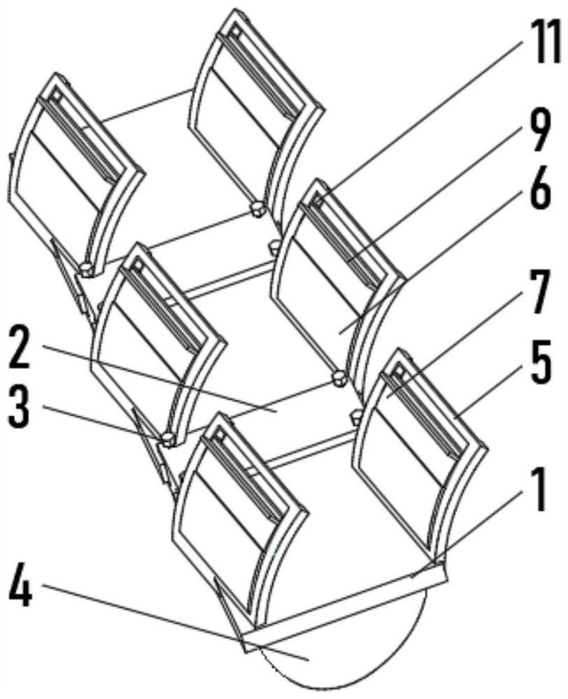
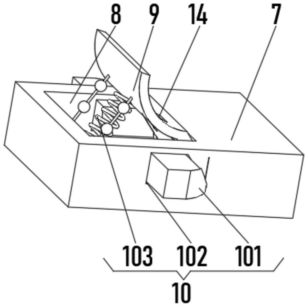
[0029] see Figure 1-2 , the present invention provides a technical solution: a wind-resistant assembled bridge, including a support plate 1, a splicing frame 2 is installed between the support plates 1, the splicing frame 2 is fixedly connected to the support plate 1 through bolts 3, and the support plate 1 The bottom is fixedly connected with an outer bump 4, the top of the support plate 1 is equipped with a protective outer frame 5, the inner bottom of the protective outer frame 5 is fixedly connected with a storage frame 6, and a lifting plate 7 is slidingly connected between the two sides of the inner wall of the storage frame 6 One side of the lifting plate 7 is provided with a push-up groove 8, and one side of the inner wall of the push-up groove 8 is rotatably connected with a push-up plate 9, and the inside of the push-up groove 8 is provided with a storage device 10.
[0030] The storage device 10 includes a spacer 101, the side of the spacer 101 close to the push-up...
Embodiment 2
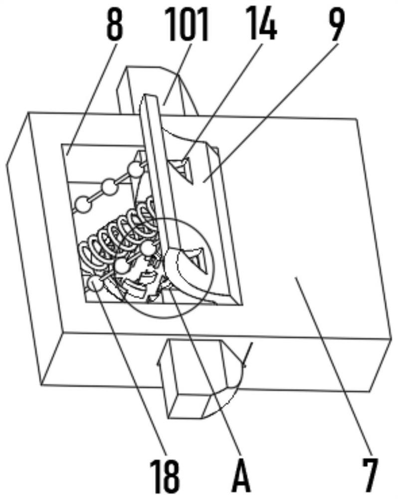
[0033] see Figure 1-4 , the present invention provides a technical solution: on the basis of Embodiment 1, the top of the push-up plate 9 is symmetrically provided with an air filling port 14, the inner bottom of the push-up groove 8 is provided with a warning circular groove 15, and the bottom of the push-up plate 9 The pull rope 17 is fixedly connected with the inner wall of the push-up groove 8 , and the outside of the pull rope 17 is uniformly equipped with metal balls 18 .
[0034] The inside of the warning circular groove 15 is uniformly equipped with arc-shaped protrusions 16 , one side of the arc-shaped protrusions 16 is fixedly connected with a metal convex cone 19 , and both the arc-shaped protrusions 16 and the metal convex cones 19 are slidably connected with the metal ball 18 .
[0035] When in use, the wind passes through the air filling port 14 when passing through the bridge, the push-up plate 9 is pulled into the push-up groove 8 by the converging spring 103,...
Embodiment 3
[0037] see Figure 1-5 , the present invention provides a technical solution: on the basis of Embodiment 1, a deceleration groove 12 is provided on one side of the storage frame 6, both ends of the deceleration groove 12 run through the storage frame 6, and a deceleration device is installed inside the deceleration groove 12 13.
[0038]The deceleration device 13 includes a swing rod 131, one end of the swing rod 131 is fixedly connected with a knocking plate 132, one side of the knocking plate 132 is evenly equipped with an impact bump 133, and one side of the inner wall of the deceleration groove 12 is fixedly connected with a heating plate 134, One side of the heating plate 134 is provided with a concave groove matching with the impact bump 133 .
[0039] One side of the swing rod 131 is uniformly provided with a wind-shielding groove 135 , and one side of the storage frame 6 is connected with an air outlet 136 at a position close to the deceleration groove 12 .
[0040] ...
PUM
 Abstract
Description
Claims
Application Information
 - Generate Ideas
- Intellectual Property
- Life Sciences
- Materials
- Tech Scout
- Unparalleled Data Quality
- Higher Quality Content
- 60% Fewer Hallucinations
Browse by: Latest US Patents, China's latest patents, Technical Efficacy Thesaurus, Application Domain, Technology Topic, Popular Technical Reports.
© 2025 PatSnap. All rights reserved.Legal|Privacy policy|Modern Slavery Act Transparency Statement|Sitemap|About US| Contact US: help@patsnap.com


