
Friction riveting device for thermoplastic carbon fiber composite material and aluminum alloy and riveting method of friction riveting device

A technology of composite materials and riveting devices, which can be applied to other household appliances, household components, household appliances, etc., and can solve problems such as connection failure, cracks, and small plastic deformation

Pending Publication Date: 2021-05-18
JILIN UNIV
View PDF0 Cites 1 Cited by
  • Summary
  • Abstract
  • Description
  • Claims
  • Application Information

AI Technical Summary

Problems solved by technology

[0003] As thermoplastic carbon fiber composites are more and more widely used in car bodies, the difficulty that comes with them is that when connecting with traditional metal materials, some common connection methods such as gluing, riveting and welding, in the connection of these lightweight requirements Various technical and economical drawbacks can arise when using materials, leading to failure or high cost of the connection
As a brittle material, carbon fiber composite material has very little plastic deformation during deformation, and its ductility is much worse than that of metal materials. In severe cases, cracks or even fractures may occur during riveting, which will affect the performance of joints.

Method used


Image

  • Friction riveting device for thermoplastic carbon fiber composite material and aluminum alloy and riveting method of friction riveting device
  • Friction riveting device for thermoplastic carbon fiber composite material and aluminum alloy and riveting method of friction riveting device
  • Friction riveting device for thermoplastic carbon fiber composite material and aluminum alloy and riveting method of friction riveting device

Examples


Embodiment Construction

[0048] The present invention will be further described in detail below in conjunction with the accompanying drawings, so that those skilled in the art can implement it with reference to the description.

[0049] Thermoplastic composites can produce plastic flow effects after being heated to a certain temperature, and restore their original properties after cooling, so the softening flow properties of thermoplastic composites at high temperatures can be used to connect dissimilar materials.

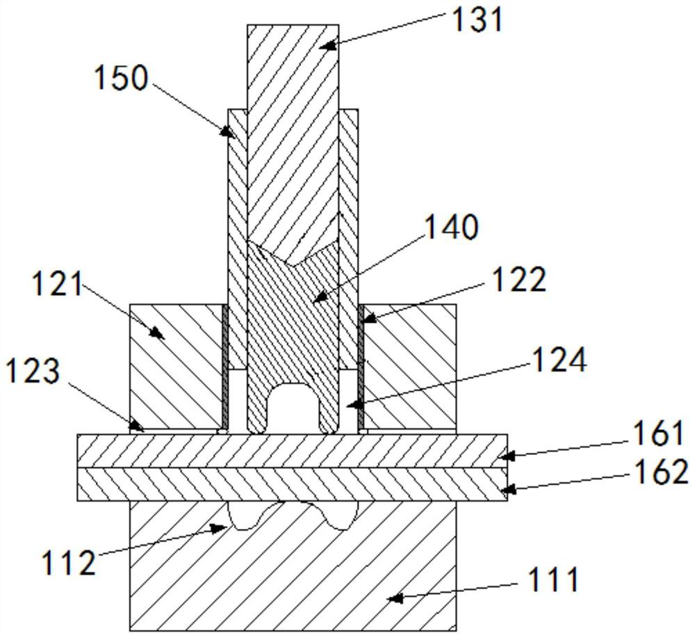
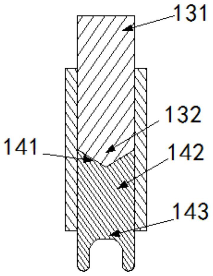
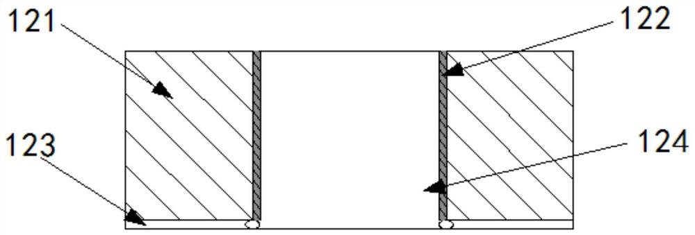
[0050] Such as figure 1 As shown, the friction riveting device between thermoplastic carbon fiber composite material and aluminum alloy according to the present invention specifically includes: die 111, blank holder 121, vacuum insulation tube 122, via hole 123, driving rod 131, rivet 140, rivet Cover 150 and connector, wherein, the lower part of the die 111 is a solid cylindrical structure, the center of the upper part is provided with a circular groove 112, and the bottom surface of the ...


PUM

PropertyMeasurementUnit
Top diameteraaaaaaaaaa
Depthaaaaaaaaaa
Heightaaaaaaaaaa

Abstract

The invention discloses a friction riveting device for a thermoplastic carbon fiber composite material and an aluminum alloy. The friction riveting device comprises a female die, a blank holder and a driving rod. The lower part of the female die is of a solid cylindrical structure, the center of the upper part of the female die is provided with a circular groove, and the bottom face of the circular groove protrudes upwards to form a conical shape. The blank holder is of a cylindrical structure, a cylindrical center hole is formed in the center of the blank holder, and the blank holder is arranged above the female die and is coaxial with the female die. The driving rod is coaxially arranged in the center hole and can perform rotary motion and axial feeding motion along the center hole. The invention further discloses a riveting method of the friction riveting device for the thermoplastic carbon fiber composite material and the aluminum alloy, heat is generated through rotating friction, meanwhile, the rotating speed and the axial feeding speed of the rivet are adjusted, and therefore the optimal rivet welding state value between the thermoplastic carbon fiber composite material plate and the aluminum alloy plate can be achieved, and the joint strength and the joint forming effect are improved.

Description

technical field [0001] The invention relates to the technical field of riveting of a thermoplastic carbon fiber composite material plate and an aluminum alloy plate, and more specifically, the invention relates to a friction riveting device and a riveting method for a thermoplastic carbon fiber composite material and aluminum alloy plate. Background technique [0002] Under the requirements of automobile lightweight, composite materials and light alloy materials are used as the main lightweight materials in light structure products. Thermoplastic carbon fiber composites have outstanding characteristics such as high toughness, high impact resistance and damage tolerance, unlimited prepreg storage period, short molding cycle, recyclable utilization, and easy repair. They have the advantages of environmental protection, high efficiency and high performance. The application is more and more extensive. [0003] As thermoplastic carbon fiber composites are more and more widely us...

Claims


Application Information

Patent Timeline
IPC IPC(8): B29C65/60B29C65/78B29L31/30
CPCB29C65/601B29C65/78B29L2031/3005
Inventor 庄蔚敏肖璐王相超杨晓文王恩铭陈沈石佳宁
Owner JILIN UNIV
Learn More