A CNC machining center capable of clamping special-shaped workpieces

A technology of special-shaped workpiece and machining center

Active Publication Date: 2022-07-05
东莞市亿东数控科技有限公司
View PDF14 Cites 1 Cited by
  • Summary
  • Abstract
  • Description
  • Claims
  • Application Information

AI Technical Summary

Problems solved by technology

[0003] There are still some deficiencies in the existing CNC machining. First of all, most of the workpieces are limited and fixed by weldments, fixing sleeves or limit plates at present, but there are still some unstable phenomena in the clamping of special-shaped workpieces. The accuracy of CNC machining is reduced; secondly, the interior of the existing CNC machining center lacks lighting devices, which is not convenient for operators to observe the processing status of workpieces and affects the processing quality

Method used


Image

  • A CNC machining center capable of clamping special-shaped workpieces
  • A CNC machining center capable of clamping special-shaped workpieces
  • A CNC machining center capable of clamping special-shaped workpieces

Examples


Embodiment 1

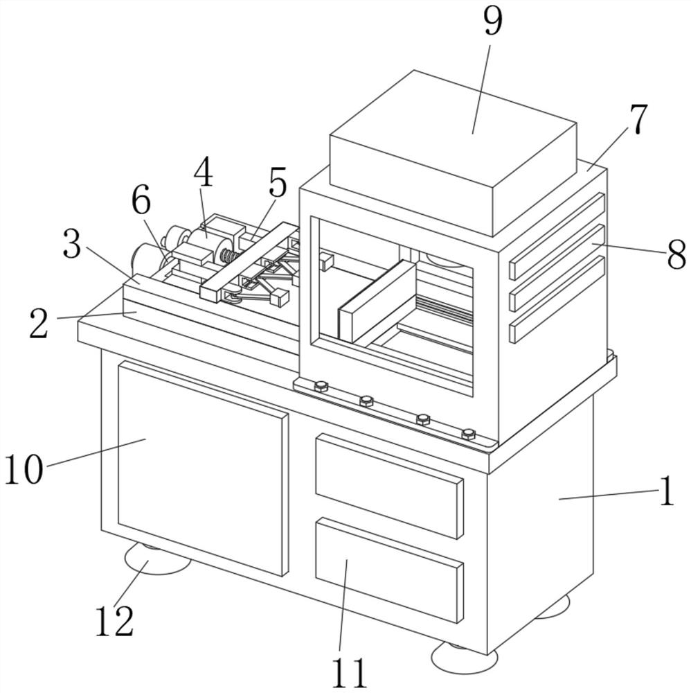
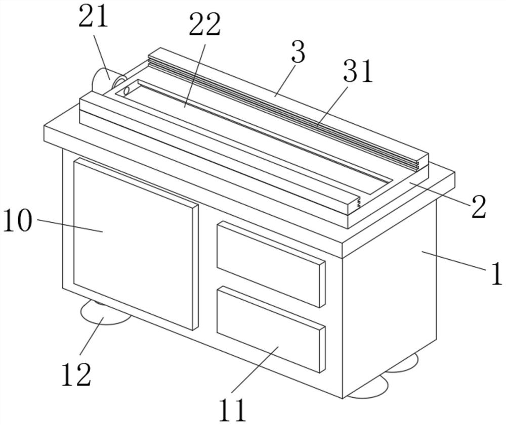
[0034] A CNC machining center capable of holding special-shaped workpieces, such as Figure 1-2 As shown, it includes an operating table 1, a fixed backing plate 2 is fixedly installed in the middle of the upper end of the operating table 1, a fixed seat 21 is fixedly welded on the left end of the fixed backing plate 2, and a chute 22 is opened in the middle of the upper end of the fixed backing plate 2 , a side support plate 3 is fixedly installed on the front and rear sides of the upper end of the fixed backing plate 2, two sliding rails 31 are opened on the opposite ends of the two side support plates 3, and a moving mechanism 4 is slidably connected in the sliding groove 22. And the front and rear ends of the moving mechanism 4 are slidably connected with the slide rails 31, an electric telescopic rod 6 is fixedly installed in the fixed seat 21, and the electric telescopic rod 6 is fixedly connected with the left end of the moving mechanism 4, and the upper end of the moving ...

Embodiment 2

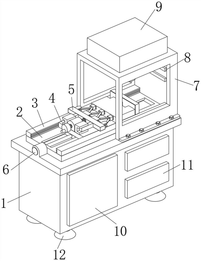
[0037] On the basis of Example 1, as Figure 3-7 As shown in the figure, a CNC machining center capable of clamping special-shaped workpieces includes an operation table 1, a fixed backing plate 2 is fixedly installed in the middle of the upper end of the operating table 1, and a fixed seat 21 is fixedly welded on the left end of the fixed backing plate 2. A chute 22 is opened in the middle of the upper end of the backing plate 2 , a side brace 3 is fixedly installed on both the front and rear sides of the upper end of the fixed backing plate 2 , and two sliding rails 31 are opened on the opposite ends of the two side braces 3 . A moving mechanism 4 is slidably connected in the chute 22 , and the front and rear ends of the moving mechanism 4 are slidably connected with the slide rail 31 . The left end is fixedly connected, the upper end of the moving mechanism 4 is screwed with a positioning mechanism 5 on the right side, and a protective frame 7 is detachably installed on the...

Embodiment 3

[0040] On the basis of Example 1, as Figure 8 As shown in the figure, a CNC machining center capable of clamping special-shaped workpieces includes an operation table 1, a fixed backing plate 2 is fixedly installed in the middle of the upper end of the operating table 1, and a fixed seat 21 is fixedly welded on the left end of the fixed backing plate 2. A chute 22 is opened in the middle of the upper end of the backing plate 2 , a side brace 3 is fixedly installed on both the front and rear sides of the upper end of the fixed backing plate 2 , and two sliding rails 31 are opened on the opposite ends of the two side braces 3 . A moving mechanism 4 is slidably connected in the chute 22 , and the front and rear ends of the moving mechanism 4 are slidably connected with the slide rail 31 . The left end is fixedly connected, the upper end of the moving mechanism 4 is screwed with a positioning mechanism 5 on the right side, and a protective frame 7 is detachably installed on the r...


PUM


Abstract

The invention discloses a numerical control machining center capable of clamping a special-shaped workpiece, comprising an operation table, a fixed backing plate is fixedly installed in the middle of the upper end of the operating table, and a side support plate is fixedly installed on the front and rear sides of the upper end of the fixed backing plate. The opposite ends of the two side braces are provided with two sliding rails, a moving mechanism is slidably connected in the sliding groove, and the front and rear ends of the moving mechanism are slidingly connected with the sliding rails, and an electric telescopic rod is fixedly installed in the fixed seat. And the electric telescopic rod is fixedly connected with the left end of the moving mechanism, a positioning mechanism is threadedly connected to the upper left side of the moving mechanism, a protective frame is detachably installed on the right side of the upper end of the operating table, and three lighting mechanisms are detachably installed on the right end of the protective frame. . The invention can fix the three contact surfaces of the special-shaped workpiece at the same time, has strong operation safety, has the lighting function, is convenient for observation, and is convenient for disassembly and installation.

Description

technical field [0001] The invention relates to the field of numerical control machining equipment, in particular to a numerical control machining center capable of clamping a special-shaped workpiece. Background technique [0002] CNC machining refers to a process method for processing parts on CNC machine tools. The process rules of CNC machine tool processing and traditional machine tool processing are generally consistent, but there have also been significant changes. Digital information is used to control parts and components. The machining method of tool displacement is an effective way to solve the problems of variable variety of parts, small batches, complex shapes and high precision, and to achieve efficient and automated processing. [0003] There are still some shortcomings in the existing CNC machining. First of all, most of the workpieces are limited and fixed by welding parts, fixed sleeves or limit plates, but there are still some unstable phenomena for the cl...

Claims


Application Information

Patent Timeline
Patent Type & Authority Patents(China)
IPC IPC(8): B23Q3/06B23Q11/00
CPCB23Q3/065Y02P90/02
Inventor 费聿娟
Owner 东莞市亿东数控科技有限公司
Why Eureka
Try Eureka