
Pneumatic tool wear early warning system and early warning method thereof

A technology of pneumatic tooling and early warning system, which is used in measuring devices, instruments, measuring fluid pressure, etc., can solve the problem of difficult to achieve early warning of pneumatic tooling wear

Pending Publication Date: 2021-04-30
UNITED AUTOMOTIVE ELECTRONICS SYST
View PDF19 Cites 0 Cited by
  • Summary
  • Abstract
  • Description
  • Claims
  • Application Information

AI Technical Summary

Problems solved by technology

In addition, in the actual production process, only the quality supervision of the processed parts is usually carried out, and the production equipment is inspected after the fact (after the abnormality / failure occurs)
Therefore, it is difficult to realize the early warning of pneumatic tooling wear, and avoid the imminent production loss (product loss, production equipment loss) caused by pneumatic tooling

Method used


Image

  • Pneumatic tool wear early warning system and early warning method thereof
  • Pneumatic tool wear early warning system and early warning method thereof

Examples


no. 1 example

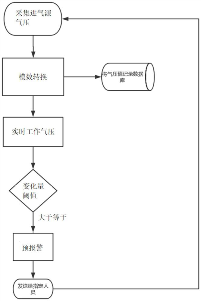
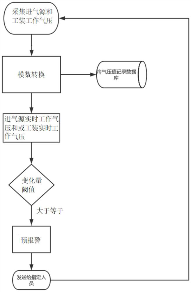
[0088] The present invention provides a first embodiment of a method for early warning of pneumatic tool wear, which includes the following steps:

[0089] 1) Collect the real-time working air pressure of the air intake source of the pneumatic tooling;

[0090] 2) If the real-time working air pressure change of the intake air source is greater than or equal to the preset air pressure change threshold working condition occurs, it is judged that the pneumatic tooling is worn, and an early warning of tooling wear is output.

[0091] The preset air pressure change threshold is 100%-1000% air pressure change, and this embodiment adopts 100%, 200%, 300%, 400%, 600%, 700%, 800%, 900% or 1000%.

no. 2 example

[0092] The present invention provides a second embodiment of a method for early warning of pneumatic tool wear, which includes the following steps:

[0093] 1) Collect the real-time working air pressure of the air intake source of the pneumatic tooling;

[0094] 2) If the real-time working air pressure change of the intake air source is greater than or equal to the preset air pressure change threshold working condition occurs at least twice, then it is judged that the pneumatic tooling is worn, and an early warning of tooling wear is output.

[0095] The preset air pressure change threshold is that the air pressure change amount is 100%-1000% (here, the change amount, that is, the air pressure may be increased or decreased, and may be doubled or halved). 100%, 200%, 300%, 400%, 600%, 700%, 800%, 900%, or 1000%.

no. 3 example

[0096] The present invention provides a third embodiment of a pneumatic tool wear early warning method, which includes the following steps:

[0097] 1) Collect the real-time working air pressure of the air intake source of the pneumatic tooling;

[0098] 2) If the real-time working air pressure change of the intake air source is greater than the preset air pressure change threshold for at least two times within the preset period, it is judged that the pneumatic tooling is worn, and an early warning of tooling wear is output.

[0099] The preset time period range is 0.1ms-10ms. In this embodiment, 0.1m, 0.2ms, 0.2ms, 0.3ms, 0.4ms, 0.5ms, 0.6ms, 0.7ms, 0.8ms, 0.9ms, 1ms, 2ms are used , 3ms, 4ms, 5ms, 6ms, 7ms, 8ms, 9ms or 10ms. The preset air pressure change threshold is 100%-1000% air pressure change, and this embodiment adopts 100%, 200%, 300%, 400%, 600%, 700%, 800%, 900% or 1000%.


PUM


Abstract

The invention discloses a pneumatic tool wear early warning system, which comprises a first connector piece, a first air pressure sensor, a digital-to-analog conversion module, a programmable logic controller and a display alarm terminal, wherein the first connector piece is connected with a first air pressure connector of a pneumatic tool, the first air pressure sensor collects the real-time working air pressure of the first air pressure connector, the digital-to-analog conversion module carries out analog-to-digital conversion on the real-time working air pressure I, which is sent by the first air pressure sensor, of the tool and then sends the real-time working air pressure I of the tool to the programmable logic controller, the programmable logic controller enables the real-time working air pressure I of the tool to form a real-time working air pressure curve I of the tool, and the display alarm terminal judges whether to output a tool wear early warning to the display alarm terminal or not according to the real-time working air pressure curve I. The invention further discloses a pneumatic tool wear early warning method. According to the invention, early warning can be carried out on the working condition that the product or the tool cannot reach the designed position to damage the product or the tool due to abnormal fluctuation of the pressure of the air inlet source and / or the working pressure of the pneumatic tool, economic loss is avoided, and the practicability and safety of the pneumatic tool are improved.

Description

technical field [0001] The invention relates to the field of automobiles, in particular to a pneumatic frock wear warning system used on automobile production lines with air pressure as the power source. The invention also relates to a method for early warning of wear of pneumatic tooling. Background technique [0002] It is a very common technical choice to use air pressure as the power source of production equipment in the modern manufacturing industry. Equipment using air pressure as the power source is widely used in the manufacturing industry, that is, the pneumatic tooling referred to in this application. A more conventional application scenario of pneumatic tooling on the automobile production line is the processing of raw materials. [0003] Take the process of grinding the inner cavity in the production process of a certain part as an example, the action flow: the air pressure drives the ejector rod to push the part into the fixture -> the fixture holds the part...

Claims


Application Information

Patent Timeline
Patent Type & Authority Applications(China)
IPC IPC(8): G01L19/12G01L19/08
CPCG01L19/12G01L19/083
Inventor 阙弓徐劲劲黄伏虎钱渊
Owner UNITED AUTOMOTIVE ELECTRONICS SYST
Learn More