
An optical camera communication demodulation method supporting receiver shaking and user movement

A user-moving, optical camera technology, applied in image communication, telephone structure, color TV components, etc., can solve the problem of few demodulation algorithms, excessive fluctuation of the average value of the demodulation performance column gray level, and poor anti-noise performance. and other problems, to achieve the effect of slowing down the interference between pixels, alleviating the sampling frequency offset, and reducing the behavior requirements.

Active Publication Date: 2021-12-21
JILIN UNIV
View PDF0 Cites 0 Cited by
  • Summary
  • Abstract
  • Description
  • Claims
  • Application Information

AI Technical Summary

Problems solved by technology

Studies have shown that this type of communication system is relatively sensitive to the user's position and local shaking. However, in actual operation, the randomness of the user's receiving position and the shaking of the receiver or user movement during the shooting process will bring inaccurate data information.
In addition, in the OCC system, due to the progressive scanning characteristics of rolling shutter exposure, the number of pixel columns corresponding to each stripe decreases with the increase of the system bit rate. When using conventional demodulation methods for demodulation, the number of pixel columns The average value of the gray level fluctuates as the bit rate increases, making it impossible to obtain accurate data information
For example, the current threshold-based discriminant demodulation algorithm, its demodulation performance is susceptible to environmental noise (such as uneven illumination) and the above-mentioned excessive fluctuation of the average value of the column gray level, and the demodulation method cannot Solve the problem that the user is in a random position and shakes and moves; in addition, the current demodulation algorithm based on the width of the stripes is judged by calculating the number of pixels occupied by the stripes. However, in the actual operation process, due to the existence of environmental noise and each The number of pixels occupied by stripes is very small. In the case of high speed, it is extremely susceptible to noise interference, so it cannot improve the communication speed. The two mainstream demodulation methods mentioned above are based on single-point pixels. Modulation and decoding, its bit error rate is high, and its anti-noise performance is poor
[0003] At home and abroad, there are few researches on the application of OCC technology in actual scenes and innovative demodulation algorithms for different shooting angles of users, and there are corresponding technical gaps.

Method used


Image

  • An optical camera communication demodulation method supporting receiver shaking and user movement
  • An optical camera communication demodulation method supporting receiver shaking and user movement
  • An optical camera communication demodulation method supporting receiver shaking and user movement

Examples


Embodiment Construction

[0047] In order to make the technical solutions and advantages of the present invention clearer, the technical solutions of the present invention will be described completely and clearly below in conjunction with the accompanying drawings in the examples of the present invention. It should be pointed out that if there are any processes or symbols that are not specifically described in detail below, those skilled in the art can refer to the prior art. The key of the present invention lies in the technical solution proposed for the demodulation structure, involving software or programming content Those skilled in the art can refer to existing implementations.

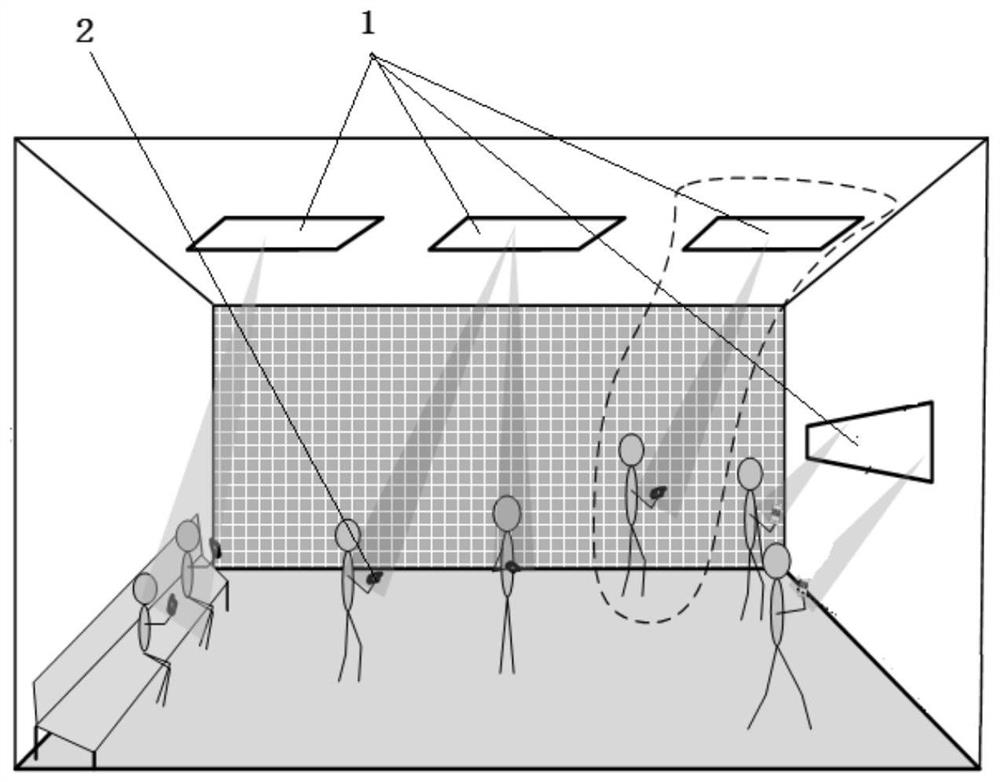
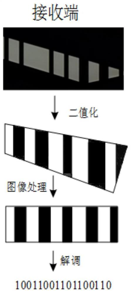
[0048] Such as figure 1 , 2 As shown, the user obtains the LED stripe video within the communication range through the smartphone camera, and obtains a stripe image with alternate light and dark stripes. Further, since the position of the LED light source is a fixed position in the space, and the position of the user in...


PUM


Abstract

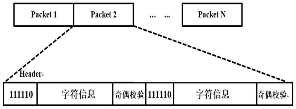
The present invention relates to an optical camera communication demodulation method supporting shaking of the receiver and user movement. The method is as follows: acquire the LED stripe video carrying the original sending data, extract each frame of stripe image; grayscale and binary the stripe image process and extract edge features to obtain a binarized fringe image; convert the binarized fringe image into a regular fringe image, and then use the fringe area demodulation method to restore the data to the regular fringe image; the original sending data adopts Manchester encoding, The data packet contains pilot information. The present invention can ignore the impact of "blossom effect" on data, is more resistant to environmental noise, improves the communication rate, solves the randomness of multi-user shooting positions and the problem of shaking and moving, has the characteristics of low complexity and strong anti-noise performance, and is easier Accurately recover the data signal.

Description

technical field [0001] The invention belongs to the technical field of visible light camera imaging communication, and relates to a demodulation technology for solving receiver shaking or user movement by using the area of ​​bright and dark stripes obtained by photographing a light source using the rolling shutter exposure characteristics of a smart phone camera. Background technique [0002] With the continuous development of science and technology, the technology applied to OCC (Optic Camera Communication) by smart phones is becoming more and more mature. CMOS uses a rolling shutter (Rolling Shutter Mechanism), and the rolling shutter exposure effect adopts a progressive exposure method. Using this feature can increase the data rate of visible light imaging communication. At each moment, the CMOS image sensor has only one row of exposure. When all rows of the image are exposed, the data of all rows of exposure captured at different times are combined to form an image. This...

Claims


Application Information

Patent Timeline
Patent Type & Authority Patents(China)
IPC IPC(8): H04N5/21H04N5/217H04N5/225H04N5/238H04N5/357H04M1/02
Inventor 迟学芬姜科宇籍风磊武敬陈少琦李帅
Owner JILIN UNIV
Learn More