Reconfigurable dual-beam periodic leaky-wave antenna

A leaky wave antenna, periodic technology, applied in the field of communication antenna, to achieve the effect of flexible and changeable beam coverage

Active Publication Date: 2021-12-03
SUN YAT SEN UNIV
View PDF10 Cites 0 Cited by
  • Summary
  • Abstract
  • Description
  • Claims
  • Application Information

AI Technical Summary

Problems solved by technology

[0007] However, the above-mentioned existing technologies can realize the reconfigurable radiation pattern of the leaky wave antenna at a fixed frequency, but the existing research only converts frequency scanning into electronic scanning, and its radiation pattern is still single-beam radiation

Method used


Image

  • Reconfigurable dual-beam periodic leaky-wave antenna
  • Reconfigurable dual-beam periodic leaky-wave antenna
  • Reconfigurable dual-beam periodic leaky-wave antenna

Examples


Embodiment 1

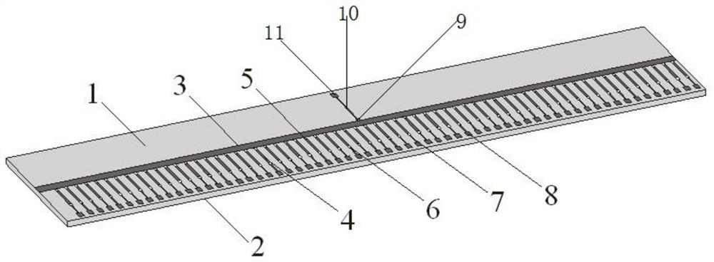
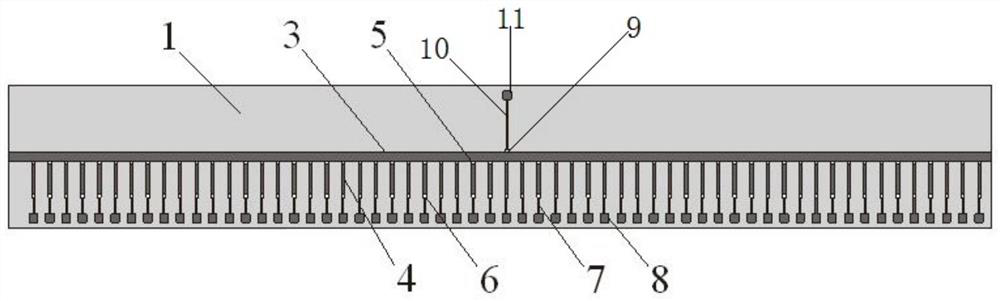
[0047] Such as figure 1 , figure 2 , image 3 As shown, a reconfigurable dual-beam periodic microstrip leaky wave antenna includes a metal floor 2, a microstrip line 3, a stub 4, a dielectric plate 1, a PIN diode 5, a first inductor 6, a first direct Current bias line 7, first DC pad 8, second inductor 9, second DC bias line 10, second DC pad 11;

[0048]The microstrip line 3 and the stub line 4 are located on the upper surface of the dielectric board 1, and the metal floor 2 is located on the lower surface of the dielectric board 1;

[0049] One end of the PIN diode 5 is connected to one side of the microstrip line 3, and the other end of the PIN diode 5 is connected to one end of the stub 4; the other end of the stub 4 is connected to one end of the first inductance 6 connection; the other end of the first inductor 6 is connected to one end of the first DC bias line 7; the other end of the first DC bias line 7 is connected to the first DC pad 8;

[0050] The PIN diode 5...


PUM

PropertyMeasurementUnit
lengthaaaaaaaaaa
widthaaaaaaaaaa
widthaaaaaaaaaa

Abstract

The invention discloses a reconfigurable dual-beam periodic microstrip leaky-wave antenna. The antenna comprises a metal floor, a microstrip line, a stub line, a dielectric plate, a PIN diode, a first inductor, a first direct current bias line, a first direct current bonding pad, a second inductor, a second direct current bias line and a second direct current bonding pad. The microstrip line and the stub line are located on the upper surface of the dielectric plate, and the metal floor is located on the lower surface of the dielectric plate; the PIN diode is connected with the microstrip line, and the PIN diode is connected with the stub line; the stub line is connected with the first inductor; the first inductor is connected with the first direct current bias line; the first direct current bias line is connected with the first direct current bonding pad; each radiation unit is formed by the PIN diode, the stub line, the PIN diode, the first inductor, the first direct current bias line and the first direct current bonding pad, and the stub line serves as a radiation element; the plurality of radiation units are arranged; the second inductor is connected with the microstrip line, and the second inductor is sequentially connected with the second direct current bias line and the second direct current bonding pad; and feed probes are arranged at the two ends of the microstrip line.

Description

technical field [0001] The present invention relates to the technical field of communication antennas, and more specifically, to a reconfigurable dual-beam periodic leaky-wave antenna. Background technique [0002] Leaky wave antenna is an attractive traveling wave antenna with simple structure, can provide frequency scanning beam, narrow beam, high gain and low profile. Most periodic leaky wave antennas introduce a series of periodic discontinuities (openings or slits) into a waveguide structure to generate radiation. Using the theory of space harmonics, the periodic aperture field is expanded into infinite space harmonic terms, in which fast waves can radiate and slow waves are bound on the antenna aperture as surface waves. The radiation of this type of antenna is contributed by n=-1 spatial harmonics, which appear as a single-beam radiation pattern. Switchable beams can be obtained by changing the frequency of the leaky wave antenna. However, this property poses chall...

Claims


Application Information

Patent Timeline
Patent Type & Authority Applications(China)
IPC IPC(8): H01Q1/36H01Q1/50H01Q13/08H01Q3/00H01Q1/48
CPCH01Q1/36H01Q1/50H01Q13/08H01Q3/00H01Q1/48
Inventor 刘菊华陈锡伦
Owner SUN YAT SEN UNIV
Why Eureka
Try Eureka