
Rolling bearing intelligent fault diagnosis method based on vibration signals

A rolling bearing and fault diagnosis technology, applied in the testing of mechanical components, testing of machine/structural components, instruments, etc., can solve the problems of dispersion, small data sample database, missing key information, etc., and achieve easy precision, increased dimensionality, and coverage The effect of a wide speed range

Active Publication Date: 2021-04-16
WUHAN UNIV OF TECH
View PDF11 Cites 0 Cited by
  • Summary
  • Abstract
  • Description
  • Claims
  • Application Information

AI Technical Summary

Problems solved by technology

[0004]In the existing technology for fault diagnosis of rolling bearings, the vibration signals of rolling bearings are usually steady-state test data and do not include rotational speed signals, which often misses key information, resulting in The diagnostic error is not easy to guarantee; and the PC is used as the processor, and the data sample database is relatively small and scattered, which is not conducive to the real-time training and accuracy improvement of the intelligent learning model; in addition, the convolutional neural network model is used for deep learning to realize automatic fault diagnosis. However, the convolutional neural network model requires a large enough training library to ensure the accuracy of the model. It is not the best choice for fault diagnosis of rolling bearings, which has relatively few fault types.

Method used


Image

  • Rolling bearing intelligent fault diagnosis method based on vibration signals
  • Rolling bearing intelligent fault diagnosis method based on vibration signals
  • Rolling bearing intelligent fault diagnosis method based on vibration signals

Examples


Embodiment Construction

[0052] The following will clearly and completely describe the technical solutions in the embodiments of the present invention with reference to the drawings in the embodiments of the present invention.

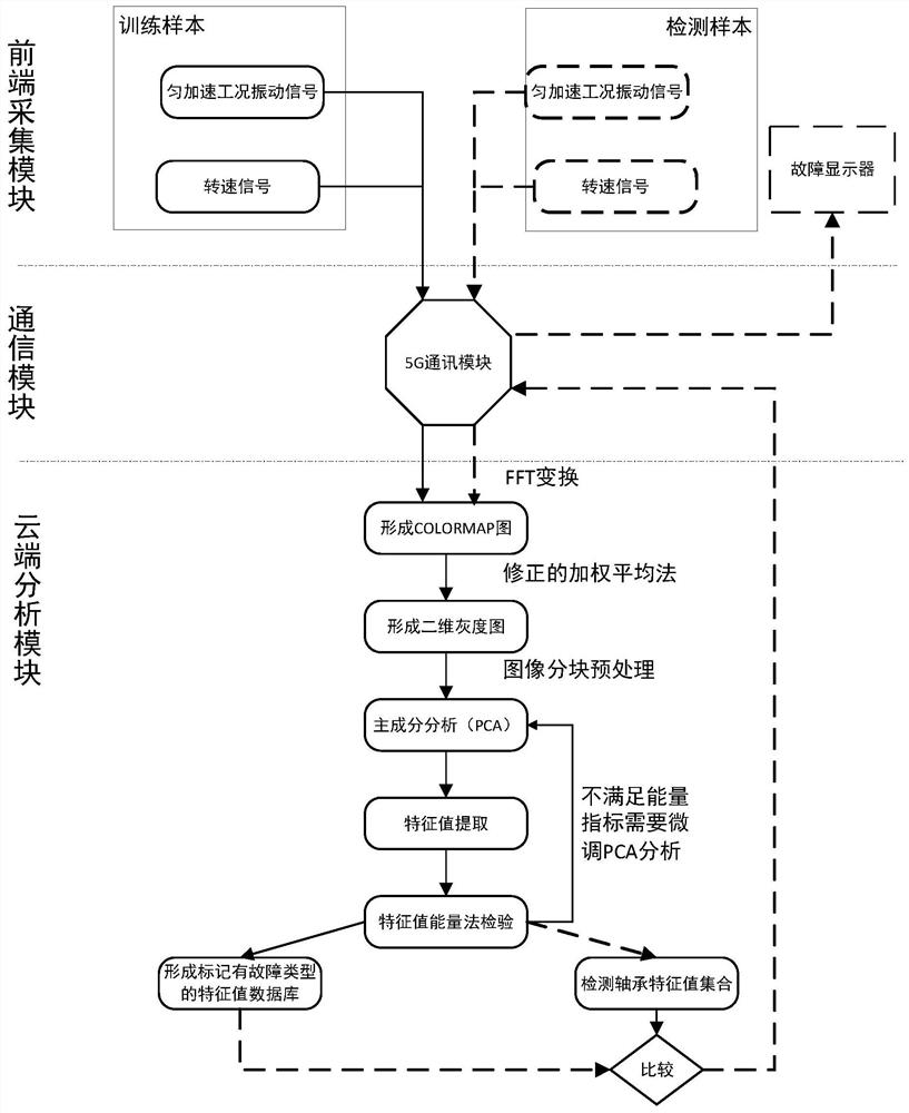
[0053] An intelligent fault diagnosis method for rolling bearings based on vibration signals, referring to figure 1 shown, including:

[0054] Step 1. Collect the three-way vibration acceleration signal and speed signal of the rolling bearing to be tested through the front-end acquisition module. The slow acceleration working condition is set according to the type of the rolling bearing to be tested and the information of the application equipment, and the rolling bearing to be tested is slowly accelerated from zero speed to the maximum speed. The speed, vibration time domain signal and speed time domain signal are preprocessed, sampled, quantized, and coded to realize data collection. The vibration signal adopts the uniform acceleration condition from zero to the highest spee...


PUM


Abstract

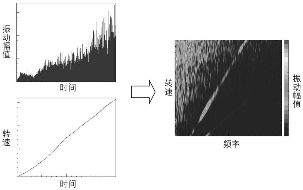
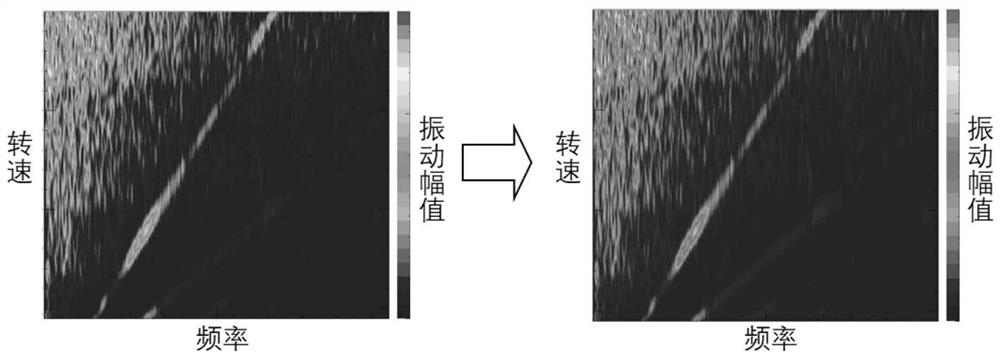
The invention discloses a rolling bearing intelligent fault diagnosis method based on vibration signals, and the method comprises the steps: collecting and detecting a three-way vibration acceleration signal and a rotating speed signal of a to-be-detected rolling bearing through a front-end collection module, and transmitting a vibration time domain signal and a rotating speed time domain signal to a cloud data processing module in real time through a 5G communication transmission module; processing a vibration time domain signal and a rotating speed time domain signal through a cloud analysis module, converting the vibration time domain signal and the rotating speed time domain signal into a vibration frequency domain signal and a rotating speed frequency domain signal through fast Fourier transform, synthesizing a coloramap, and displaying resonance, order, impact and low-energy, medium-high-frequency band distribution information through the coloramap; converting a coloramap into a two-dimensional grey-scale map, establishing an intelligent learning model, analyzing and extracting feature point information in the two-dimensional grey-scale map, carrying out feature recognition, adopting signals under a uniform acceleration working condition, increasing rotational speed signal acquisition, increasing dimensions on vibration signals, improving basic information amount and improving precision.

Description

technical field [0001] The invention relates to the technical field of bearing fault diagnosis, in particular to an intelligent fault diagnosis method for rolling bearings based on vibration signals. Background technique [0002] Rolling bearings widely exist in rotating machinery, and the damage of their state will seriously affect the running state and performance realization of rotating machinery. Therefore, the state detection and fault diagnosis of rolling bearings have always been the direction of people's attention. With the development of sensor technology, it is more convenient to obtain a large amount of test data from mechanical equipment, thus promoting the development of fault diagnosis technology based on test signals. [0003] In the fault diagnosis of rolling bearings, Fourier transform (FFT), wavelet transform (WPT) and empirical mode decomposition (EMD) based on vibration signals are all common diagnostic techniques. Analyze and extract features from time...

Claims


Application Information

Patent Timeline
Patent Type & Authority Applications(China)
IPC IPC(8): G06K9/00G06K9/46G06K9/62G01M13/045
Inventor 卢炽华李永超刘志恩宋伟志安宏杰
Owner WUHAN UNIV OF TECH
Learn More