
Novel optical fiber temperature measurement system of transformer station high-voltage switch cabinet

A high-voltage switchgear, optical fiber temperature measurement technology, applied in substation/switch layout details, substation/switchgear board/panel/desk, substation/power distribution device shell, etc., can solve the contact operating temperature in high-voltage switchgear Difficult to monitor, heating of components, difficult to measure and other problems, achieve simple and reliable alarm mode, anti-electromagnetic interference, and solve the effects of difficult monitoring

Pending Publication Date: 2021-04-16
国网河南省电力公司超高压公司 +1
View PDF8 Cites 0 Cited by
  • Summary
  • Abstract
  • Description
  • Claims
  • Application Information

AI Technical Summary

Problems solved by technology

The 35kV high-voltage switchgear is used as a large number of diversion equipment in the power system. During the long-term operation of the equipment, the components in it will cause heat due to oxidation, dust, looseness, overload, poor contact, etc., and the heating parts are likely to cause safety hazards.
[0005] In order to effectively solve the above problems, the inventors of the present application researched on the temperature measurement technology of high-voltage switchgear, considering the characteristics of high-voltage switchgear such as narrow space, closed structure, difficult measurement, high voltage, etc., and analyzed the parts that are prone to failure and the generation of high-voltage switchgear in the environment of high-voltage switchgear form, and the failure mechanism was studied, and the finite element temperature analysis was carried out; a fiber-optic fiber-optic on-line temperature monitoring technology was proposed, and the sensor was placed on the high-voltage contact inside the switch cabinet to fundamentally solve the problem of contact operation in the high-voltage switch cabinet. Difficulty in temperature monitoring

Method used


Image

  • Novel optical fiber temperature measurement system of transformer station high-voltage switch cabinet
  • Novel optical fiber temperature measurement system of transformer station high-voltage switch cabinet
  • Novel optical fiber temperature measurement system of transformer station high-voltage switch cabinet

Examples


Embodiment 1

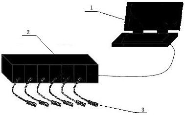
[0034] Such as figure 1 Shown is a schematic structural diagram of a new type of optical fiber temperature measurement system for a substation high-voltage switchgear provided by the present invention, including a lower computer and six optical fiber method-percent sensors connected to it through six channels. The lower computer communicates through USB Connect with the host computer; the host computer completes data communication, multi-channel data decoding, real-time display of multi-channel data, saves data and subsequent processing work; the lower computer completes multi-channel optical fiber method-Person sensing signal acquisition , processing, demodulation and complete communication with the host computer.

[0035] The main function of the upper computer is to complete the data display and subsequent processing. Using a PC, it sends control commands to the lower computer through USB communication, completes data communication, multi-channel data decoding, real-time di...

Embodiment 2

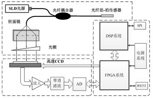
[0046] According to the design of the temperature measurement system provided by this application, six channels are used, and the multi-channel is a parallel structure, so each channel needs a demodulation module structure. The demodulation module structure is the core optical module of each channel, and the optical fiber is completed for each channel. The F-P non-scanning correlation operation is used to obtain the correlation signal between the fiber F-P sensor and the optical wedge.

[0047] The light source is divided into six paths to reach the sensor through a 3×6 fiber optic coupler, and the light carrying sensor information enters the demodulation optical path of each module. The difference between this embodiment and the embodiment is that the demodulation module includes a cylindrical mirror, Optical wedges, photodetectors, and optical wedges are the key optical devices for demodulating and realizing correlation operations to obtain related signals, and their quality ...

Embodiment 3

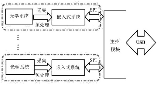
[0053] According to the system structure diagram and the functions of each part, the hardware system design of this system is mainly the design of the hardware system of the lower computer. The lower computer is further divided into: six-channel optical fiber method - Perco sensor acquisition and demodulation module and the main control module. The main function of the optical fiber method-Pertinent sensing acquisition and demodulation module is to complete the acquisition, processing and demodulation of the optical fiber method-Pertinent non-scanning related demodulation signal after receiving the instruction, and send the demodulation result to the main control module. The main control module is responsible for communicating with the upper computer, receiving and interpreting instructions, controlling each channel to start working in a specific mode, and sending the demodulation results of each acquisition and demodulation module to the upper computer.

[0054] The embedded ...


PUM

PropertyMeasurementUnit
wavelengthaaaaaaaaaa

Abstract

The invention belongs to the technical field of transformer substation switch cabinet temperature measurement, and particularly relates to a novel optical fiber temperature measurement system of a transformer substation high-voltage switch cabinet which comprises a lower computer and a plurality of optical fiber Fabry-Perot sensors connected with the lower computer through multiple channels, and the lower computer is connected with an upper computer through USB communication. The upper computer completes data communication, multi-channel data decoding, real-time display of multi-channel data, data storage and subsequent processing; the lower computer completes multichannel optical fiber Fabry-Perot sensing signal acquisition, processing and demodulation and completes communication with the upper computer. The system can achieve real-time on-line monitoring of the internal temperature of the closed high-voltage switch cabinet, is not electrified, has the advantages of intrinsic explosion prevention, lightning protection, corrosion prevention, electromagnetic interference resistance and the like, and can achieve real-time on-line monitoring of the internal temperature of large power cable equipment.

Description

technical field [0001] The invention belongs to the technical field of temperature measurement of a substation switch cabinet, and in particular relates to a novel optical fiber temperature measurement system of a high-voltage switch cabinet of a substation. Background technique [0002] The transformer is an important electrical equipment. During the long-term operation of the equipment, the connecting rods, fixing parts, coils, iron cores and other parts of the transformer will generate heat due to factors such as resistance and magnetic flux leakage. This heat will in turn cause the oil temperature to rise. , causing the transformer insulating oil to decompose, affecting the quality of the oil, increasing the internal pressure of the transformer, reducing the insulation performance of the insulating oil, causing the transformer to explode and burn, causing accidents and large-scale power outages. Under the normal working condition of the transformer, the temperature of th...

Claims


Application Information

Patent Timeline
Patent Type & Authority Applications(China)
IPC IPC(8): G01K11/32H02B1/32H02B1/24H02B1/04H02B1/28
Inventor 汤会增郭凯张利张高峰陈凯郭果
Owner 国网河南省电力公司超高压公司
Learn More