
A magnetic field-assisted lightening device and method for complex curved surfaces based on alternating magnetic field

A technology of alternating magnetic field and complex curved surface, which can be used in grinding drive devices, parts of grinding machine tools, grinding/polishing equipment, etc. Achieve the effect of flexible operation flexibility, increase reliability, and improve finishing efficiency

Active Publication Date: 2022-05-13
SHANDONG UNIV OF TECH
View PDF15 Cites 0 Cited by
  • Summary
  • Abstract
  • Description
  • Claims
  • Application Information

AI Technical Summary

Problems solved by technology

Although magnetorheological technology solves this problem to a certain extent, under high-shear finishing conditions, the viscosity of magnetorheology will decrease, thereby weakening the grip on magnetic abrasive grains, reducing the finishing effect, and being affected by Due to the limited size of the device, it is still difficult to be used for finishing of complex curved surfaces

Method used


Image

  • A magnetic field-assisted lightening device and method for complex curved surfaces based on alternating magnetic field
  • A magnetic field-assisted lightening device and method for complex curved surfaces based on alternating magnetic field
  • A magnetic field-assisted lightening device and method for complex curved surfaces based on alternating magnetic field

Examples


specific Embodiment approach 1

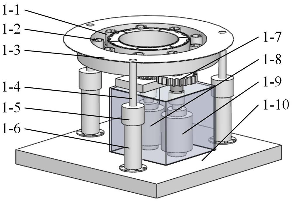
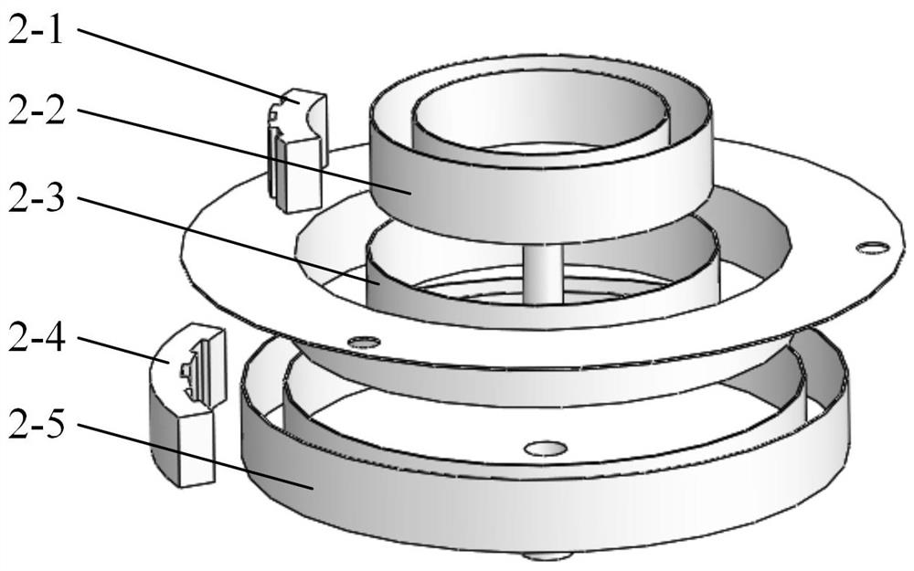
[0019] Specific implementation mode one: combine figure 1 , figure 2 and image 3 Description The device in this embodiment includes a workpiece clamping device (1-2), a magnetic field generating device (1-3), a vibration connecting rod (1-4), a vibration motor (1-5), a supporting connecting rod (1- 6), the gear transmission mechanism (1-7), the inner annular magnetic pole groove driving motor (1-8), the outer annular magnetic pole groove driving motor (1-9) and the base (1-10), the magnetic field generating device (1 -3) Including inner annular magnetic pole (2-1), inner annular magnetic pole slot (2-2), annular baffle (2-3), outer annular magnetic pole (2-4) and outer annular magnetic pole slot (2-5) , the inner annular magnetic pole slot (2-2) equipped with the inner annular magnetic pole (2-1) is fixedly connected to the main shaft of the inner annular magnetic pole slot driving motor (1-8), and is equipped with the outer annular magnetic pole (2-4) The outer annular m...

specific Embodiment approach 2

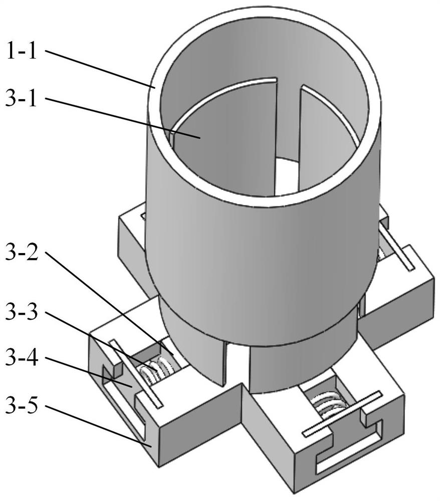
[0020] Specific implementation mode two: combination image 3 Description The workpiece clamping device (1-2) in this embodiment includes a stopper (3-1), a slider (3-2), a spring (3-3), a spring stopper (3-4) and a base ( 3-5), the retainer (3-1) is fixedly connected to the slider (3-2), one end of the spring (3-3) is connected to the slider (3-2), and the other end is fixed to the spring On the baffle (3-4), the spring baffle (3-4) is installed on the base (3-5) through interference fit, and the parts to be processed can be realized by adjusting the position of the baffle (3-1). 1-1) Clamping of different surfaces. When the stopper (3-1) is moved to make it close to the inner surface / outer surface of the part to be processed (1-1), since the spring (3-3) is in a stretched / compressed state, it is elastic Restoration force, so that the block (3-1) is tightly pressed against the inner surface / outer surface of the part to be processed, and the clamping of different surfaces of...

specific Embodiment approach 3

[0021] Specific implementation mode three: combination figure 1 Description In this embodiment, the frequency controller is used to adjust the working mode of the vibration motor (1-5) to control the trajectory of abrasive grains, thereby improving the finishing efficiency. The ring baffle (2-3) uses three vibration motors (1-5) Vibrate to ensure that the annular baffle (2-3) can receive sufficient excitation force and the magnitude of the excitation force is uniform and equal, and ensure that when a certain vibration motor (1-5) fails In this state, it can still work normally, which increases the reliability of the device. Others are the same as those of the specific embodiment 1 or 2.

[0022] Specific implementation plan four: combination figure 2 and Figure 4 Explain that the inner annular magnetic pole groove (2-2) of this embodiment can hold 6 inner annular magnetic poles (2-1), and the outer annular magnetic pole groove (2-5) can hold 6 outer annular magnetic poles ...


PUM


Abstract

Aiming at the technical problems of high-efficiency, high-quality finishing and flexible control of complex curved surfaces, a magnetic field-assisted finishing device and method for complex curved surfaces based on alternating magnetic fields were invented. The device includes a workpiece clamping device, a magnetic field generating device, a vibrating connecting rod, a vibrating motor, a supporting connecting rod, a gear transmission mechanism, an inner annular magnetic pole groove driving motor, an outer annular magnetic pole groove driving motor and a base, and the magnetic field generating device includes Inner annular magnetic poles, inner annular magnetic pole slots, annular baffles, outer annular magnetic poles and outer annular magnetic pole slots. Among them, the workpiece clamping device can realize the clamping of different surfaces of the parts to be processed; adjust the rotation direction and speed of the inner and outer ring magnetic poles, generate an alternating magnetic field, and drive the magnetic finishing medium to carry out finishing processing; the three vibration motors Vibration composite action further improves the finishing efficiency. The invention can break through the limitation of the traditional method on complex curved surface finishing, so as to realize efficient flexible automatic finishing.

Description

technical field [0001] The invention relates to a complex curved surface magnetic field assisted finishing technology, and in particular provides a complex curved surface magnetic field assisted finishing device and a finishing method based on an alternating magnetic field. Background technique [0002] As a typical surface finishing technology, finishing technology can reduce and refine surface roughness, remove scratches, microscopic cracks and other surface defects, thereby improving surface processing quality, improving surface finish, and realizing stable control of parts precision. Traditional finishing techniques such as manual grinding, extrusion honing, and mechanical polishing have certain limitations in terms of processing efficiency, precision, quality, and degree of automation, and are only suitable for finishing of small batches of parts. Aiming at the problems of traditional mechanical polishing, a series of finishing technologies such as magnetic field-assist...

Claims


Application Information

Patent Timeline
Patent Type & Authority Patents(China)
IPC IPC(8): B24B1/00B24B41/06B24B47/20
Inventor 田业冰孙志光范增华钱乘
Owner SHANDONG UNIV OF TECH
Learn More