
A counter-lifting mechanism for railway locomotive wheels

A lifting mechanism and locomotive technology, applied in the direction of lifting frame, lifting device, etc., can solve the problems of increasing the workload of staff, inconvenient maintenance, danger, wheelset shaking, etc. Effect

Active Publication Date: 2022-02-18
吉林铁道职业技术学院
View PDF0 Cites 1 Cited by
  • Summary
  • Abstract
  • Description
  • Claims
  • Application Information

AI Technical Summary

Problems solved by technology

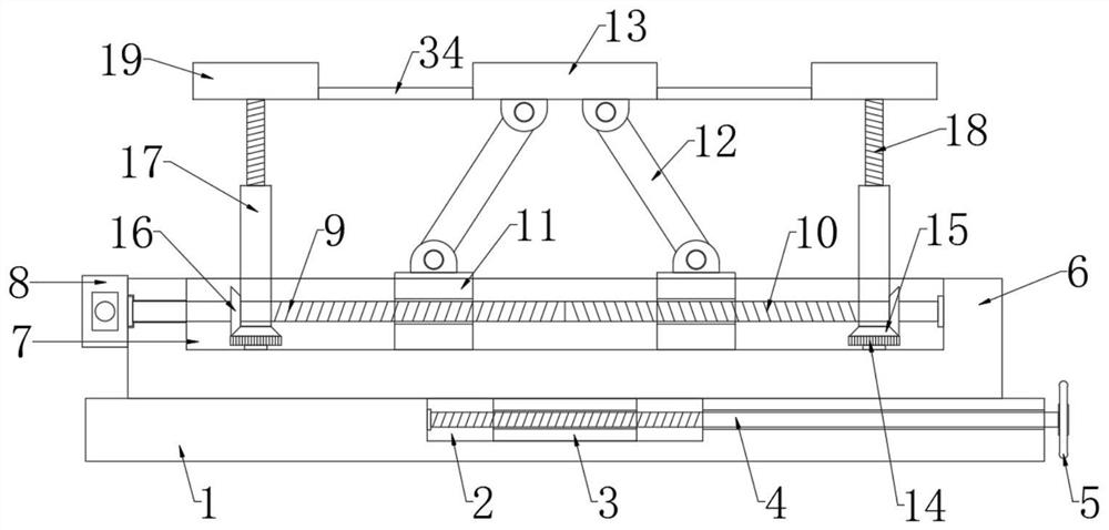
[0003] Existing railway locomotives and subway vehicles need to support the wheel sets to facilitate the maintenance of the wheels when performing maintenance on the opposite wheel sets; It makes the hoisted wheel set shake, which is inconvenient for maintenance and has certain dangers; the other is supported by a support plate, which is more stable than the gantry hoisting, but the axle is still manually fixed and limited during support, which increases The workload of the staff is reduced, so we designed a lifting mechanism for railway locomotive wheels to solve the above problems

Method used


Image

  • A counter-lifting mechanism for railway locomotive wheels
  • A counter-lifting mechanism for railway locomotive wheels
  • A counter-lifting mechanism for railway locomotive wheels

Examples


Embodiment Construction

[0021] The following will clearly and completely describe the technical solutions in the embodiments of the present invention with reference to the accompanying drawings in the embodiments of the present invention. Obviously, the described embodiments are only some, not all, embodiments of the present invention.

[0022] In describing the present invention, it should be understood that the terms "upper", "lower", "front", "rear", "left", "right", "top", "bottom", "inner", " The orientation or positional relationship indicated by "outside", "front end", "rear end", "both ends", "one end" and "the other end" are based on the orientation or positional relationship shown in the drawings, and are only for the convenience of describing this The invention and the simplified description do not indicate or imply that the device or element referred to must have a specific orientation, be constructed and operate in a specific orientation, and thus should not be construed as limiting the p...


PUM


Abstract

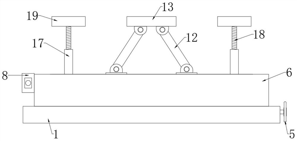
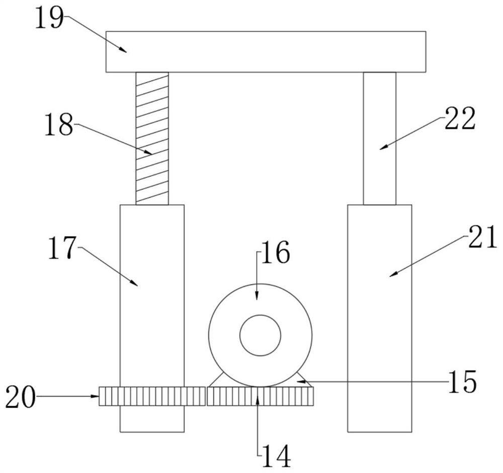
The invention discloses a lifting mechanism for railway locomotive wheels, which comprises a base, a sliding seat is slidably connected to the base, an adjustment mechanism is arranged between the sliding seat and the base, and a sliding seat is provided on the sliding seat. Two sliding blocks are slidably connected in the sliding groove, and a servo motor is fixedly connected to the sliding seat; the limit mechanism includes a U-shaped groove arranged in the first U-shaped support plate and the second U-shaped support plate A reset plate is slidably connected in the U-shaped groove, a plurality of first springs are fixedly connected between the reset plate and the inner bottom of the U-shaped groove, and two guide columns are fixedly connected to the upper end of the reset plate. The invention has a reasonable structure, not only can stably support the wheel set, but also can stably clamp the axle to ensure its stability after being supported, without manual operation by the staff, greatly reducing the workload of the staff, and More security.

Description

technical field [0001] The invention relates to the technical field of lifting devices, in particular to a lifting mechanism for railway locomotive wheels. Background technique [0002] The wheel set is the part of the rolling stock that is in contact with the rail, and consists of two left and right wheels that are firmly pressed on the same axle. The role of the wheel set is to ensure the running and turning of the rolling stock on the rails, bear all the static and dynamic loads from the rolling stock, transmit it to the rail, and transfer the load caused by the uneven track to the parts of the rolling stock. In addition, the driving and braking of the rolling stock also work through the wheelset. [0003] Existing railway locomotives and subway vehicles need to support the wheel sets to facilitate the maintenance of the wheels when performing maintenance on the opposite wheel sets; It makes the hoisted wheel set shake, which is inconvenient for maintenance and has cert...

Claims


Application Information

Patent Timeline
Patent Type & Authority Patents(China)
IPC IPC(8): B66F7/06B66F7/28
CPCB66F7/0608B66F7/28
Inventor 姜海莲
Owner 吉林铁道职业技术学院
Learn More