
Throttling type killing manifold with lifting base

A technology of kill manifold and lifting base, which is applied in the direction of casing, drill pipe, drilling equipment, etc. It can solve the problems of inconvenient construction of support height, no lifting of the base, cumbersome work, etc., and achieves convenient installation, reasonable structure and simple operation square effect

Active Publication Date: 2020-12-04
DONGYING HUACHEN PETROLEUM EQUIP CO LTD
View PDF10 Cites 1 Cited by
  • Summary
  • Abstract
  • Description
  • Claims
  • Application Information

AI Technical Summary

Problems solved by technology

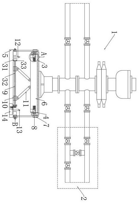
[0003] However, the base of the existing choke-type kill manifold is mostly installed on the ground, or on a support on the ground. The base of the existing choke-type kill manifold has no lifting function, and in actual use, the It is to meet the needs of actual use by building brackets of different heights, but it is inconvenient to build the height of the brackets, and the work is cumbersome and the efficiency is low. Therefore, we designed a throttle-type kill manifold with a lifting base to solve the above problems. question

Method used


Image

  • Throttling type killing manifold with lifting base
  • Throttling type killing manifold with lifting base
  • Throttling type killing manifold with lifting base

Examples


Embodiment Construction

[0024] The following will clearly and completely describe the technical solutions in the embodiments of the present invention with reference to the accompanying drawings in the embodiments of the present invention. Obviously, the described embodiments are only some, not all, embodiments of the present invention.

[0025] In describing the present invention, it should be understood that the terms "upper", "lower", "front", "rear", "left", "right", "top", "bottom", "inner", " The orientation or positional relationship indicated by "outside", "front end", "rear end", "both ends", "one end" and "the other end" are based on the orientation or positional relationship shown in the drawings, and are only for the convenience of describing this The invention and the simplified description do not indicate or imply that the device or element referred to must have a specific orientation, be constructed and operate in a specific orientation, and thus should not be construed as limiting the p...


PUM


Abstract

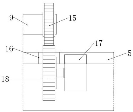
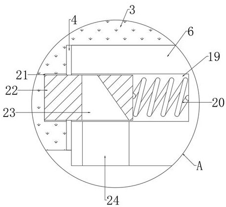
The invention discloses a throttling type killing manifold with a lifting base, and relates to the technical field of oil exploitation. The throttling type killing manifold comprises a killing manifold and a choke manifold, wherein the choke manifold is connected with the killing manifold; the lifting base is arranged at the bottom of the killing manifold; a support base is arranged below the lifting base; a plurality of limiting mechanisms are arranged between the support base and the lifting base; a mounting groove is arranged in the bottom of the lifting base; a connecting base is arrangedin the mounting groove, the connecting base is connected to the mounting groove through a clamping mechanism; two positioning blocks are fixedly connected to the support base; and a first screw and asecond screw are respectively arranged on two bearings. The throttling type killing manifold is reasonable in structure, capable of rapidly adjusting the height of the killing manifold, easy, convenient and rapid to operate, capable of meeting the requirements in actual use and high in working efficiency, meanwhile, the lifting base can be detached to be conveniently placed on the ground, and thesupport base and the killing manifold can be conveniently transported.

Description

technical field [0001] The invention relates to the technical field of petroleum exploitation, in particular to a throttling type kill manifold with a lifting base. Background technique [0002] Killing manifold is a term used in oil production. The function of killing manifold is to force the mud to be filled through the killing manifold to carry out the well killing operation when the wellhead is sealed with a fully sealed ram; when a blowout occurs When the well is blown out, clean water is forcibly injected into the wellhead through the kill manifold to prevent burning; when the blowout is on fire, the fire extinguishing agent is forcibly injected into the wellbore through the kill manifold to assist in extinguishing the fire; The flow-type kill manifold and the throttle-type kill manifold are installed with a throttle valve or a throttle valve group. The function of the throttle valve is to adjust the flow rate, generate throttle pressure, and keep the bottom hole press...

Claims


Application Information

Patent Timeline
Patent Type & Authority Applications(China)
IPC IPC(8): F16L3/16E21B17/00
CPCE21B17/00F16L3/16
Inventor 刘志波赵约翰
Owner DONGYING HUACHEN PETROLEUM EQUIP CO LTD
Learn More