
Straight pipe four-direction multi-hole punching machine

A multi-hole punching and four-direction technology, which is applied in positioning devices, cleaning methods and tools, chemical instruments and methods, etc., can solve the problem of insufficient compactness of the structure of the jacking device and the punching machine, large equipment footprint, and workpiece positioning. Difficulty and other problems, to avoid manual operation accidents, long service life of equipment, and less space occupied by equipment

Pending Publication Date: 2021-04-13
浙江先创智能装备有限公司
View PDF0 Cites 0 Cited by
  • Summary
  • Abstract
  • Description
  • Claims
  • Application Information

AI Technical Summary

Problems solved by technology

Although this method achieves the purpose of directly punching the workpiece, because the positioning of the hollow workpiece is difficult, the workpiece will be deformed when the clamping force is too large during the punching process, and the workpiece will also be deformed when the punching force is applied during the punching process. thereby affecting product quality
[0004] In addition, after the punching of the workpiece, some of them use the hand-held method to remove the workpiece, which is not only inefficient, but also has a high labor intensity and a low degree of automation; The way to remove the workpiece, by adding a manipulator, not only increases the cost of the equipment, but also leads to a larger footprint of the equipment; in addition, there is also a method of adding a jacking device to the punching machine, and the workpiece is ejected through the jacking device. The workpiece is removed, but the structure of the jacking device and the punching machine is not compact enough, resulting in a larger volume of the punching machine
[0005] In addition, when the workpiece is punched, a large amount of debris will be produced, and these debris are easy to accumulate in the workpiece punching mold shell. Falling debris, but because the debris cannot be concentrated by any device, the distribution of the debris is relatively scattered, so the debris is often not all blown off, which will affect the subsequent stamping. If this is the case for a long time, it will also cause the punching mold of the workpiece damage to

Method used


Image

  • Straight pipe four-direction multi-hole punching machine
  • Straight pipe four-direction multi-hole punching machine
  • Straight pipe four-direction multi-hole punching machine

Examples


Embodiment Construction

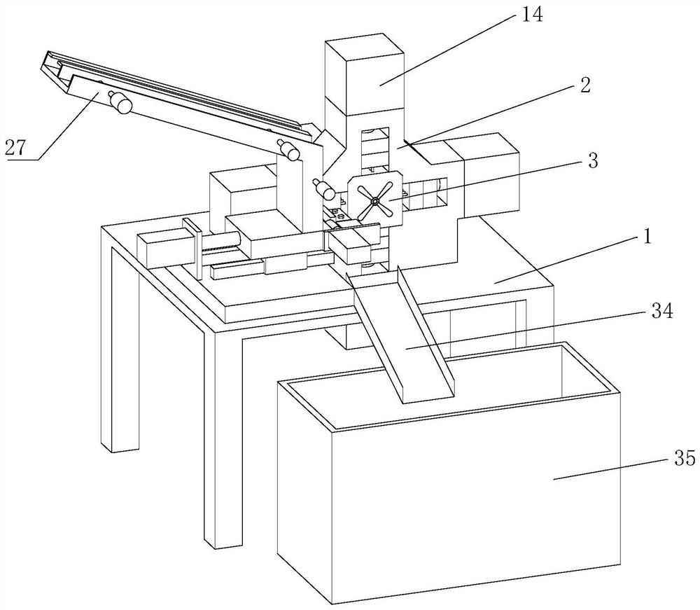
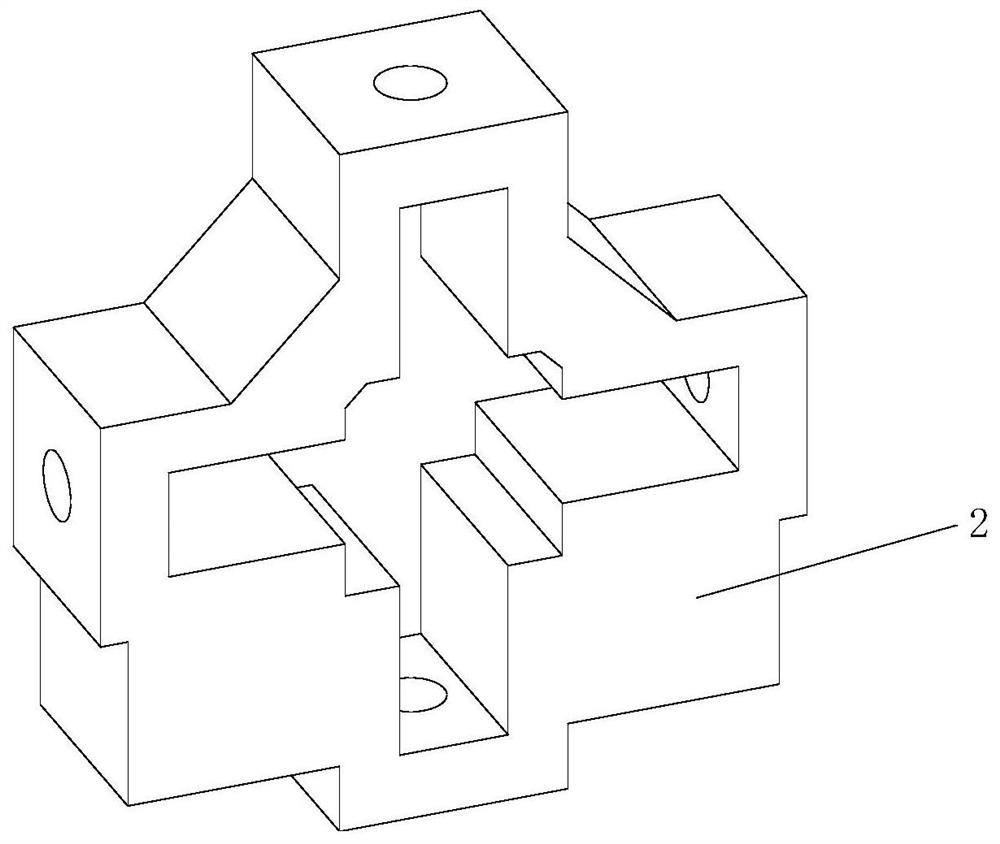
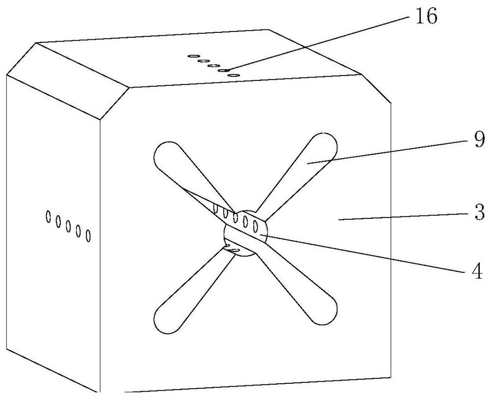
[0030] Embodiments of the present invention are described in detail below, examples of which are shown in the accompanying drawings, and the embodiments described below by referring to the accompanying drawings are exemplary and are intended to explain the present invention so that the technical solutions of the present invention It is easier to understand and grasp, but cannot be construed as a limitation to the present invention.

[0031] refer to Figure 1-8 As shown, the present invention provides a technical solution: a straight tube four-direction multi-hole punching machine, including a frame 1, on which a punching frame 2 is arranged, and the punching frame 2 is in the shape of a "ten", punching The center of the frame 2 is fixed with a mold shell 3, and the mold shell 3 is provided with a mold hole 4 that runs through the front and back. The diameter of the mold hole 4 is slightly larger than the diameter of the workpiece, so the workpiece can be placed in the mold ho...


PUM


Abstract

The invention discloses a straight pipe four-direction multi-hole punching machine, and belongs to the technical field of punching machines. The straight pipe four-direction multi-hole punching machine comprises a rack, wherein a punching frame is arranged on the rack; a die shell is fixedly arranged in the punching frame; a die hole penetrating front and back is formed in the die shell; a punching device, a positioning device and a discharging device are arranged on the punching frame; the positioning device comprises a sleeve die base arranged on the rear side of the die shell and a sleeve die column arranged in the center of the sleeve die base and stretching into the die hole to allow a workpiece to be sleeved; the sleeve die column and the sleeve die base are connected and are integrally formed; the discharging device comprises a push sleeve arranged on the outer side of the sleeve die column in a sleeving manner, at least one connecting petal connected with the outer side of the push sleeve, a channel arranged in the die shell, communicating with the die hole and matched with the connecting petal in size, a connecting rod arranged on the rear side of the connecting petal, a fixed disc connected with the rear end of the connecting rod and a discharging air cylinder driving the fixed disc to do reciprocating motion; and the discharging air cylinder is fixedly arranged on the rack. The effects of being high in automation degree, capable of preventing the workpiece from deforming in the punching process, compact in overall structure and good in chip removing effect are achieved.

Description

technical field [0001] The invention relates to the field of punching machines, in particular to a straight tube four-directional multi-hole punching machine. Background technique [0002] The silencer pipe is an important component of the silencer. In the early days of processing the silencer pipe in the industry, the original flat plate was punched first, and then bent and welded into a tubular shape. The process was complicated. low efficiency. [0003] With the development of science and technology, at present, the method of directly punching the tubular workpiece is used to make the silencer pipe in the industry. The method is: the workpiece is sent into the workpiece punching mold shell for punching, the process is simple, and the production efficiency is high. . Although this method achieves the purpose of directly punching the workpiece, because the positioning of the hollow workpiece is difficult, the workpiece will be deformed when the clamping force is too larg...

Claims


Application Information

Patent Timeline
Patent Type & Authority Applications(China)
IPC IPC(8): B21D28/28B21D28/04B21D43/02B21D45/06B08B5/02
CPCB21D28/28B21D28/04B21D43/02B21D45/06B08B5/02
Inventor 王炳万再荣胡江
Owner 浙江先创智能装备有限公司
Learn More