
Transistor forming method

A transistor and patterning technology, applied in semiconductor/solid-state device manufacturing, electrical components, circuits, etc., can solve the problems of integrated circuit manufacturing cost consumption

Pending Publication Date: 2021-04-09
CHANGXIN MEMORY TECH INC
View PDF18 Cites 3 Cited by
  • Summary
  • Abstract
  • Description
  • Claims
  • Application Information

AI Technical Summary

Problems solved by technology

Due to the need to use at least two photomasks and two photolithography processes, the manufacturing cost of integrated circuits is relatively high

Method used


Image

  • Transistor forming method
  • Transistor forming method
  • Transistor forming method

Examples


Embodiment Construction

[0024] The specific implementation of the transistor forming method provided by the present invention will be described in detail below in conjunction with the accompanying drawings.

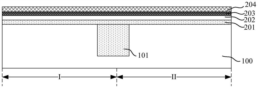
[0025] Please refer to figure 1 , a substrate 100 is provided, and the substrate 100 includes a first region I and a second region II.

[0026] The substrate 100 is a semiconductor substrate for forming semiconductor devices. The substrate 100 may be single crystal silicon, single crystal germanium, silicon germanium or silicon-on-insulator. In a specific embodiment, the substrate 100 is a single crystal silicon substrate.

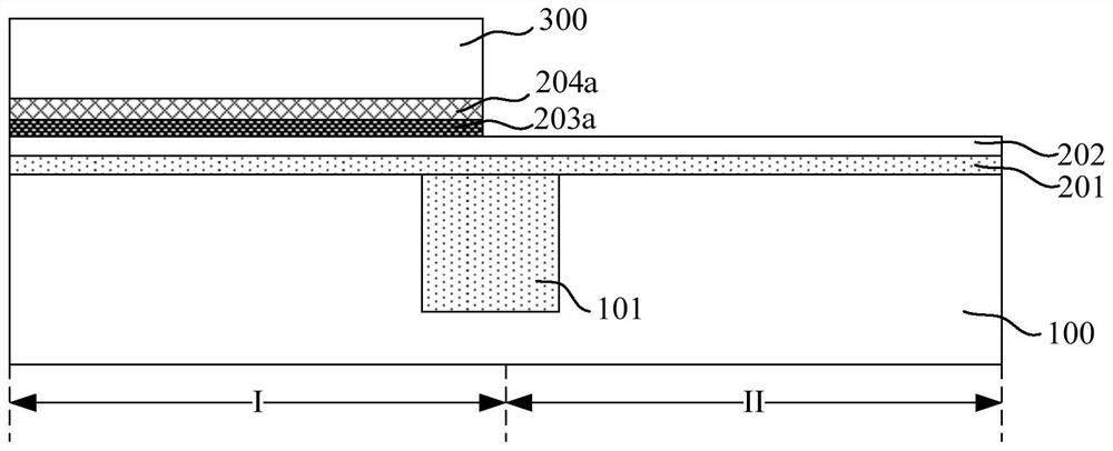
[0027] The first region I of the substrate 100 is used to form a first type transistor, and the second region II is used to form a second type transistor. In a specific implementation manner, the first type transistor is an NMOS transistor, and the second type transistor is a PMOS transistor. The first region I and the second region II are isolated by an isolation struc...


PUM

PropertyMeasurementUnit
Thicknessaaaaaaaaaa

Abstract

The invention relates to a transistor forming method comprising the steps: providing a substrate comprising a first area and a second area; sequentially forming a high-K dielectric layer, a first type covering layer and a first gate layer on the first area and the second area; removing the first gate layer and the first covering layer on the surface of the second area; forming a second covering layer covering the remaining first gate layer and the high-K dielectric layer and a second gate layer located on the surface of the second covering layer; carrying out planarization processing on the second gate layer and the second covering layer until the first gate layer is exposed; and simultaneously patterning the first gate layer, the first covering layer and the high-K dielectric layer which are positioned on the first area to form a first gate structure, and simultaneously patterning the second gate layer, the second covering layer and the high-K dielectric layer which are positioned on the second area to form a second gate structure. The method of the transistor can reduce the process cost.

Description

technical field [0001] The invention relates to the technical field of semiconductors, in particular to a method for forming a transistor. Background technique [0002] With the continuous reduction of process nodes, the gate length of transistors is continuously reduced, so that the thickness of the gate dielectric layer is also reduced to improve the short channel effect. As a traditional gate dielectric layer material, silicon oxide is no longer an ideal insulator when the thickness is small to a certain extent, and there will be obvious tunneling leakage problems. [0003] In order to solve this problem, in the prior art, a high-K dielectric material is used instead of silicon oxide as a gate dielectric layer, and metal is used as a gate material to form an HKMG transistor. For different types of HKMG transistors, different covering layers need to be formed between the gate dielectric layer (HK layer) and the metal gate (MG layer) to block the migration of metal and rea...

Claims


Application Information

Patent Timeline
IPC IPC(8): H01L21/8234H01L21/027
CPCH01L21/823437H01L21/0274
Inventor 白杰
Owner CHANGXIN MEMORY TECH INC
Learn More