
A shielded gate mosfet device and its preparation method

A shielding grid and device technology, applied in semiconductor/solid-state device manufacturing, semiconductor devices, electrical components, etc., to achieve the effect of reducing manufacturing costs

Active Publication Date: 2021-11-26
安建科技(深圳)有限公司
View PDF1 Cites 0 Cited by
  • Summary
  • Abstract
  • Description
  • Claims
  • Application Information

AI Technical Summary

Problems solved by technology

[0003] In view of the above-mentioned problems of the existing shielded trench field effect transistor devices, it is necessary to propose a shielded gate trench field effect transistor structure and process flow with simple process and low manufacturing cost

Method used

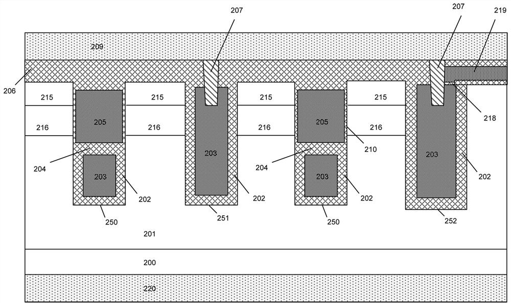
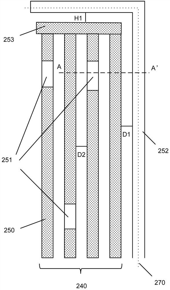
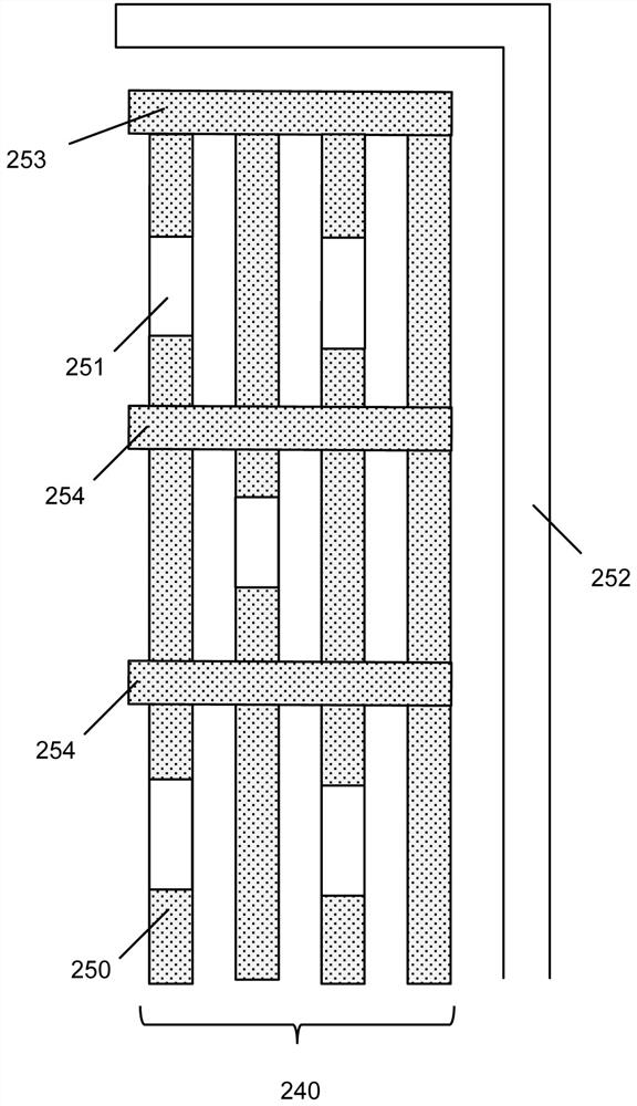

Image

  • A shielded gate mosfet device and its preparation method
  • A shielded gate mosfet device and its preparation method
  • A shielded gate mosfet device and its preparation method

Examples


Embodiment Construction

[0071] The present invention will be described in detail below in conjunction with the accompanying drawings and embodiments. It should be pointed out that in the following description of the shielded gate trench field effect transistor device and its manufacturing method of the present invention, the semiconductor substrate of the shielded gate trench field effect transistor device is considered to be made of silicon (Si) material. However, the substrate can also be made of any other material suitable for the manufacture of shielded gate trench field effect transistors, such as gallium nitride (GaN), silicon carbide (SiC) and so on. In the following description, the conductivity type of the semiconductor region is divided into P-type (second conductivity type) and N-type (first conductivity type), and a P-type conductivity type semiconductor region can be obtained by doping one or Composed of several impurities, these impurities can be but not limited to: boron (B), aluminum ...


PUM

PropertyMeasurementUnit
heightaaaaaaaaaa
thicknessaaaaaaaaaa
thicknessaaaaaaaaaa

Abstract

A shielded gate MOSFET device and its preparation method. The present invention relates to power semiconductor devices. In order to solve the problem of cumbersome and costly preparation methods of existing shielded gate trench type field effect transistor devices, the present invention provides the following technology Solution: more than one parallel series of grooves located in the epitaxial layer, the series of grooves are composed of interconnected first-type grooves and / or second-type grooves, and the series of grooves pass through horizontal grooves designed in different forms Groove connection, there is more than one third-type groove surrounding the series of grooves on the periphery of the series of grooves. The shielded gate trench type field effect transistor device proposed by the invention has a unique structure and manufacturing process.

Description

technical field [0001] The invention relates to a power semiconductor device, in particular to the structure and manufacturing method of a shielded gate trench type field effect transistor device. Background technique [0002] Shielded gate trench field effect transistor, as a new type of power device, has the characteristics of low on-resistance and fast switching speed. The structural feature of the shielded trench field effect transistor is that there are mutually isolated gate electrodes and shielded gate electrodes in the trench, wherein the shielded gate electrode is located below the gate electrode and needs to be connected to the upper surface metal. For example, in the technical solution provided by US7005351, the entire process flow requires six to eight photolithography steps. Usually, in the formation of the P body doped region and the N + For source doping regions, photolithography process steps need to be carried out using a photolithography plate, and the pro...

Claims


Application Information

Patent Timeline
Patent Type & Authority Patents(China)
IPC IPC(8): H01L29/78H01L21/336H01L29/423
CPCH01L29/4236H01L29/66484H01L29/66666H01L29/7827H01L29/7831
Inventor 单建安梁嘉进伍震威
Owner 安建科技(深圳)有限公司
Learn More