
Molten iron dross filtering structure in casting mold

A casting mold and filter structure technology, applied in the field of casting molds, can solve the problems of fragments rushing into castings, secondary slag, sand inclusions in castings, etc., and achieve the effects of improving position stability, improving impact resistance, and improving filtering effects

Pending Publication Date: 2021-04-02
苏州勤堡精密机械有限公司
View PDF1 Cites 0 Cited by
  • Summary
  • Abstract
  • Description
  • Claims
  • Application Information

AI Technical Summary

Problems solved by technology

In the prior art, what the overwhelming majority adopts is the zirconia filter sheet of honeycomb structure, and as patent publication number is that CN204094059U discloses a kind of filter screen sprue device for casting, and it has the following defects: 1) the honeycomb structure The zirconia filter is fragile, and the fragments rush into the casting, which may cause the quality risk of casting scrap; 2) The zirconia filter with honeycomb structure is easy to cause turbulent flow of molten iron and form secondary slag; 3) The filter is installed in the In the sand mold, the molten iron impacts the sand mold, which is likely to cause sand inclusions in the casting; 4) The filter is installed in the mold, and its upper surface is basically flat with the upper surface of the corresponding position of the lower mold, resulting in a gap between the filter and the upper mold. The quality of scum in water is relatively light, and it will generally be suspended on the surface of the molten iron, and the molten iron passes directly through the gap, which cannot effectively filter

Method used


Image

  • Molten iron dross filtering structure in casting mold
  • Molten iron dross filtering structure in casting mold
  • Molten iron dross filtering structure in casting mold

Examples


Embodiment 1

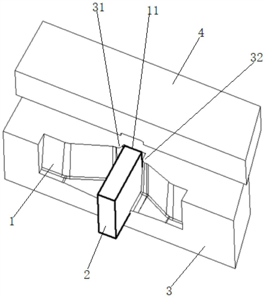
[0024] Please refer to Figure 1-Figure 5 , the present embodiment is a molten iron scum filter structure 100 in a casting mold, which includes a honeycomb filter block 2 arranged in the runner 1 and whose periphery is in contact with the inner wall surface of the runner 1. The runner 1 is formed by the lower mold 3 Surrounded by the profiling groove on the opposite surface of the upper mold 4, the upper surface of the honeycomb filter mesh block 2 protrudes from the upper surface of the lower mold 3 and the upper part is embedded in the lower surface of the upper mold 4. The width of the water inlet side is greater than the width of the water outlet side.

[0025] The runner 1 is provided with a closed groove 11 that defines the position of the honeycomb filter mesh block 2. The position of the honeycomb filter mesh block 2 is limited by the closed groove 11, and at the same time, the peripheral surface of the honeycomb filter mesh block 2 and the pouring Sealing of the inne...


PUM


Abstract

The invention discloses a molten iron dross filtering structure in a casting mold. The molten iron dross filtering structure comprises a honeycomb filter screen block arranged in a pouring gate, the periphery of the honeycomb filter screen block is attached to the surface of the inner wall of the pouring gate, the pouring gate is jointly formed by a lower mold and an upper mold in a surrounding manner, the upper surface of the honeycomb filter screen block protrudes out of the upper surface of the lower mold, the upper portion of the honeycomb filter screen block is embedded into the lower surface of the upper mold, and the width of the part, on the water inlet side of the honeycomb filter screen block, of the pouring gate is larger than that of the part, on the water outlet side, of the pouring gate. According to the molten iron dross filtering structure, position stability of a filter screen and the sealing performance of the filter screen and the periphery of the pouring gate can beguaranteed, it is guaranteed that molten iron can effectively pass through the filter screen to achieve dross filtering, and the casting forming quality is improved.

Description

【Technical field】 [0001] The invention belongs to the technical field of casting molds, in particular to a structure for filtering molten iron scum in a casting mold. 【Background technique】 [0002] Casting refers to the processing method of melting solid metal into liquid and pouring it into a mold of a specific shape, and waiting for it to solidify and form. The key to the slag avoidance design of the cavity gating system is to effectively filter the slag when the molten iron enters the predetermined design runner system. To solve this problem, in the prior art, a filter screen is provided in the gating system so that the molten iron can filter out slag and impurities before entering the cavity. In the prior art, what the overwhelming majority adopts is the zirconia filter sheet of honeycomb structure, and as patent publication number is that CN204094059U discloses a kind of filter screen sprue device for casting, and it has the following defects: 1) the honeycomb structu...

Claims


Application Information

Patent Timeline
Patent Type & Authority Applications(China)
IPC IPC(8): B22C9/08
CPCB22C9/086Y02P10/20
Inventor 徐孟兰
Owner 苏州勤堡精密机械有限公司
Learn More