Eureka AIR delivers breakthrough ideas for toughest innovation challenges, trusted by R&D personnel around the world.

Method for preparing chopped carbon fiber reinforced amorphous composite material and a device thereof

A technology of amorphous composite material and chopped carbon fiber, which is applied in the field of preparation of chopped carbon fiber reinforced amorphous composite material, can solve the problems of fast cooling speed, poor wettability, low cooling rate, etc., and achieves small negative damage and improved Wetting property, effect of improving wettability

Active Publication Date: 2021-03-26
HEBEI UNIV OF TECH
View PDF14 Cites 3 Cited by
  • Summary
  • Abstract
  • Description
  • Claims
  • Application Information

AI Technical Summary

Problems solved by technology

However, this method has a low cooling rate, it is difficult to reach more than 100K / s, and it is impossible to prepare composite materials for more amorphous alloy systems
CN101250677A discloses a titanium dioxide carbon coating carbon fiber reinforced magnesium-based composite material, which is mainly composed of matrix magnesium alloy and TiO 2 Coated carbon fiber composition, carbon fiber surface TiO 2 The coating is made by sol-gel method, and the raw material of magnesium alloy is SF 6 and CO 2 Mixed gas protection, heating up to 700°C to melt the alloy, will have TiO 2 The coated carbon fiber is preheated to 400°C, placed in a metal mold preheated to 200°C, the molten alloy liquid is cast into the metal mold, and formed under pressure, the extrusion pressure is 10MPa, and the pressure holding time is 60 seconds. TiO 2 Coated carbon fiber reinforced magnesium matrix composites, which have the disadvantage that this method is only applicable to the traditional magnesium alloy matrix, and cannot achieve a faster cooling rate and obtain an amorphous matrix
CN111155038A discloses a method for preparing a chopped carbon fiber reinforced magnesium-based composite material. The method uses a sol-gel method to prepare an oxide coating on the surface of a carbon fiber, which has a high oxygen content in the alloy and is not conducive to the non-uniformity of the matrix structure of the composite material. The preparation process of crystallization and chopped carbon fiber preform is complicated, and the methods of squeeze casting and hot extrusion are not suitable for the preparation of amorphous composite materials that require rapid solidification technology.
CN108385040B discloses a kind of chopped carbon fiber reinforced magnesium-aluminum matrix composite material and its preparation method, which does not carry out surface modification to chopped carbon fiber, so the wettability between carbon fiber and metal liquid is relatively poor, which is not conducive to the molding of composite material , when the reactivity of metal liquid and carbon fiber is high, it will intensify the interface reaction and destroy the defects of composite interface structure and mechanical properties
The above-mentioned prior art also has the defect that amorphous composite materials cannot be prepared for various amorphous alloy substrates that require vacuum melting only for magnesium-aluminum alloy substrates.
[0004] In short, the prior art has fiber agglomeration phenomenon caused by uneven dispersion of reinforcing fibers in the matrix or interfacial structure in which brittle phases are formed at the interface between carbon fiber and matrix, and is only applicable to traditional magnesium alloy matrix, which cannot achieve faster cooling rate and Obtain an amorphous matrix, and cannot design and prepare amorphous composite materials for various amorphous alloys that require vacuum melting

Method used


Image

  • Method for preparing chopped carbon fiber reinforced amorphous composite material and a device thereof
  • Method for preparing chopped carbon fiber reinforced amorphous composite material and a device thereof
  • Method for preparing chopped carbon fiber reinforced amorphous composite material and a device thereof

Examples


preparation example Construction

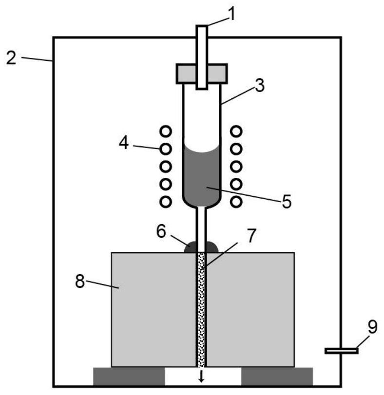
[0043] figure 1The illustrated embodiment shows that the components of the device used in the preparation method of the chopped carbon fiber reinforced amorphous composite material include: an air inlet 1, a closed high vacuum induction heating spray casting furnace body 2, a thick tube with a A quartz tube with a diameter of 0.5 mm to 2 mm nozzle 3, a water-cooled induction heating coil 4, high-temperature cement 6, a split copper mold with an inner cavity diameter of 2 mm to 30 mm 8, and a closed furnace body 2. The outlet is connected to the valve 9 of the vacuum system; the connection mode of each component of the device is: the split copper mold 8 is placed in the center of the closed furnace body 2, and the water-cooled induction heating coil 4 is arranged on the thick tube of the quartz tube 3 Around the part, the spout part of the quartz tube 3 is in contact with the inner cavity of the split copper mold 8 from the top of the split copper mold 8 and is sealed with high...

Embodiment 1

[0051] The components of the device used in the preparation method of chopped carbon fiber reinforced amorphous composite materials include: air inlet 1, a closed high vacuum induction heating spray casting furnace body 2, and a thick tube with a diameter of 0.5mm~ Quartz tube with 2mm spout 3, water-cooled induction heating coil 4, high-temperature cement 6, split copper mold with an inner cavity diameter of 2mm to 30mm 8, a closed furnace body 2 with a vacuum system connected to the gas outlet on the lower side Valve 9; the connection mode of each component of the device is: the split copper mold 8 is placed in the central position of the closed body of furnace 2, the water-cooled induction heating coil 4 is arranged around the thick tube part of the quartz tube 3, and the quartz tube The spout part of 3 is in contact with the inner cavity of the split copper mold 8 from the top of the split copper mold 8 and is sealed with high temperature cement 6 to avoid air leakage. The ...

Embodiment 2

[0056] The first step, chopped carbon fiber electroless plating:

[0057] Commercial T800 carbon fiber is used for shearing, and then sieved with a 400-mesh sieve, and the chopped carbon fiber under the sieve is taken to obtain a chopped carbon fiber with a length of 30 μm, and the chopped carbon fiber is subjected to electroless copper plating. The process includes: Pretreatment →Sensitization, activation→reduction→plating, in which the pretreatment uses the burning method and organic solvent immersion, the specific process is 1h in a heating furnace at 420°C, then soaked in acetone for 1h, then ultrasonically cleaned with alcohol for 15min, and dried Then use concentrated nitric acid to soak for 1 hour to roughen, then rinse repeatedly with clean water until all residual nitric acid is removed, and then dehydrate and dry with alcohol; for sensitization and activation, put the roughened carbon fiber into the sensitization-activation solution and mechanically stir for 15 minute...


PUM

PropertyMeasurementUnit
Diameteraaaaaaaaaa
Yield strengthaaaaaaaaaa
Diameteraaaaaaaaaa

Abstract

The invention discloses a method for preparing a chopped carbon fiber reinforced amorphous composite material and a device thereof, and relates to the technical field of forming an amorphous compositematerial by contacting fibers with molten metal and performing rapid solidification. The method adopts a chemical plating method to improve the wettability of the carbon fibers, a carbon fiber preform is prepared through a copper mold, furthermore, the chopped carbon fiber reinforced amorphous composite material is prepared by using a vacuum low-pressure casting method, namely a spray casting method, and the defects that in the prior art, the fiber agglomeration phenomenon caused by non-uniform dispersion of reinforced fibers in a matrix or an interface structure with brittleness equal to that generated by the carbon fibers and the matrix at an interface, the method is only suitable for a traditional magnesium alloy matrix, a high cooling speed cannot be achieved, an amorphous matrix cannot be obtained, and the amorphous composite material cannot be prepared for various amorphous alloy matrixes needing vacuum melting are overcome.

Description

technical field [0001] The technical solution of the present invention relates to the technical field of forming amorphous composite materials through rapid solidification by contacting fibers with molten metal, in particular to the preparation method and device of chopped carbon fiber reinforced amorphous composite materials. Background technique [0002] Due to its high specific strength, high specific modulus and good high temperature performance, carbon fiber reinforced metal matrix composites have attracted widespread attention in many high-tech fields such as automobiles, aviation and aerospace. With the rapid development of aviation technology, the proportion of various carbon fiber composite materials used in the manufacture of new passenger aircraft is increasing, showing attractive development prospects. Traditional carbon fiber reinforced metal matrix composites are mainly based on alloys such as aluminum alloys and magnesium alloys with low density and good plast...

Claims


Application Information

Patent Timeline
IPC IPC(8): C22C45/10C22C45/00C22C49/11C22C49/10C22C49/04C22C49/14C22C47/04C22C47/06C22C47/16C22C47/18B22D18/06B22D18/04C22C101/10C22C121/02
CPCC22C45/10C22C45/005C22C49/11C22C49/10C22C49/04C22C49/14C22C47/04C22C47/06C22C47/16C22C47/18B22D18/06B22D18/04
Inventor 王新尹海龙赵立臣刘水清崔春翔
Owner HEBEI UNIV OF TECH
Why Eureka
Eureka Blog
Learn More