
Concrete prefabricated part manufacturing method

A technology for concrete prefabricated parts and a production method, which is applied to manufacturing tools, auxiliary molding equipment, ceramic molding machines, etc., can solve the problems of wasted labor, waste of concrete, prone to slurry leakage, liquid leakage, etc., and maintain a clean and tidy work. environment, reducing concrete waste, and avoiding the effect of slurry leakage

Inactive Publication Date: 2021-03-16
王蒙蒙
View PDF6 Cites 0 Cited by
  • Summary
  • Abstract
  • Description
  • Claims
  • Application Information

AI Technical Summary

Problems solved by technology

[0005] The invention can solve the problem of poor mold sealing performance of the existing concrete prefabricated parts production device, which is prone to grout leakage and liquid leakage during concrete pouring, which easily causes concrete waste, and the outflowing concrete is difficult to clean, causing a messy working environment in the workshop It can also solve the problem that the existing concrete prefabricated part production device cannot automatically separate the mold from the prefabricated part after the prefabricated part is formed, and the mold needs to be removed manually, which wastes labor and is inefficient, and affects the production efficiency of concrete prefabricated parts.

Method used


Image

  • Concrete prefabricated part manufacturing method
  • Concrete prefabricated part manufacturing method
  • Concrete prefabricated part manufacturing method

Examples


Embodiment Construction

[0033] The embodiments of the present invention will be described in detail below with reference to the accompanying drawings, but the present invention can be implemented in many different ways defined and covered by the claims.

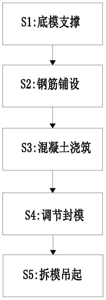
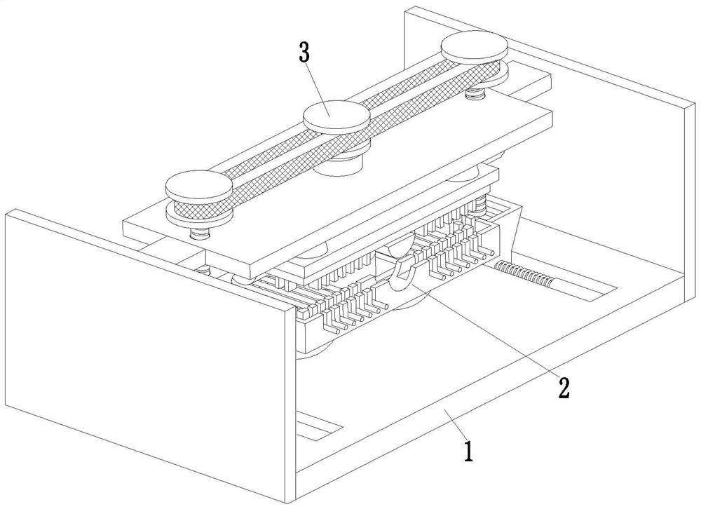
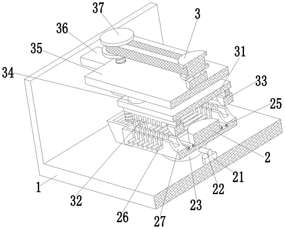
[0034] like Figure 1 to Figure 7 As shown, a concrete prefabricated production method, which uses an auxiliary concrete prefabricated production device, the auxiliary concrete prefabricated production device includes a support frame 1, an external wall mold 2 and a clamping adjustment mechanism 3, the support The frame 1 has a 匚-shaped structure with an opening upward. An outer wall mold 2 is arranged in the middle of the upper end of the support frame 1. The outer wall mold 2 is connected with a clamping adjustment mechanism 3. The clamping adjustment mechanism 3 is installed on the support frame by sliding fit. 1 on.

[0035]The exterior wall mold 2 includes an air pump 21, a three-way pipe 22, a support air bag 23, an exhaust port 24, an exteri...


PUM


Abstract

The invention relates to a concrete prefabricated part manufacturing method. The manufacturing method uses an auxiliary concrete prefabricated part manufacturing device, the auxiliary concrete prefabricated part manufacturing device comprises a supporting frame, an outer wall mold and a clamping adjusting mechanism, the supporting frame is of a left square bracket-shaped structure with an upward opening, the outer wall mold is arranged in the middle of the upper end face of the supporting frame, and the clamping adjusting mechanism is connected to the outer wall mold. According to the manufacturing method, the problems that a prefabricated part die of an existing device is poor in sealing performance, slurry leakage and liquid leakage are likely to happen during concrete pouring, concretewaste is likely to be caused, flowing-out concrete is difficult to clear, and a messy working environment is caused to a workshop can be solved, and the problems that an existing device cannot automatically separate the die from the prefabricated part after the prefabricated part is formed, the die needs to be manually disassembled, labor force is wasted, efficiency is low, and the manufacturing efficiency of the concrete prefabricated part is affected can be solved.

Description

technical field [0001] The invention relates to the technical field of concrete prefabricated parts, in particular to a method for manufacturing concrete prefabricated parts. Background technique [0002] Prefabricated parts, also known as PC components, refer to concrete products processed and produced in factories through standardized and mechanized methods. Concrete prefabricated parts refer to concrete components made of concrete products at the factory or site (not the final design position). The precast concrete is cast elsewhere rather than at the final construction site. Precast concrete of different sizes and shapes can use fibers to enhance its reliability and toughness after cracking. Prefabricated concrete can accelerate the speed of housing industrialization and is one of the key points of my country's economic system reform. With its low cost and excellent performance, prefabricated concrete has become the new favorite of the construction industry. A wide v...

Claims


Application Information

Patent Timeline
Patent Type & Authority Applications(China)
IPC IPC(8): B28B7/22B28B23/02B28B1/14B28B17/00
CPCB28B1/14B28B7/22B28B17/00B28B23/02
Inventor 王蒙蒙夏文进
Owner 王蒙蒙
Learn More