
Anti-seismic transformer box with counterweight buffer function

A transformer box and functional technology, applied in transformer/inductor casing, transformer/reactor installation/support/suspension, building type, etc., can solve problems such as circuit burnout, failure to supply power, broken circuit devices, etc., to achieve increased Stability, ensure stable operation, enhance the effect of stability

Pending Publication Date: 2021-03-12
浙江龙呈电力设备有限公司
View PDF9 Cites 1 Cited by
  • Summary
  • Abstract
  • Description
  • Claims
  • Application Information

AI Technical Summary

Problems solved by technology

[0003] Transformers are installed in transformer boxes and combined into box-type transformers. Box-type transformers are widely used power equipment in the construction and renovation of power system urban networks. With the frequent occurrence of natural disasters in recent years, strong earthquakes occurred in Wenchuan and Yushu. Now Some transformer boxes have poor anti-seismic effect. When the ground vibrates, the transformer box is easy to tilt and fall, breaking the internal circuit device, causing the circuit to burn out and failing to supply power.

Method used


Image

  • Anti-seismic transformer box with counterweight buffer function
  • Anti-seismic transformer box with counterweight buffer function
  • Anti-seismic transformer box with counterweight buffer function

Examples


Embodiment 1

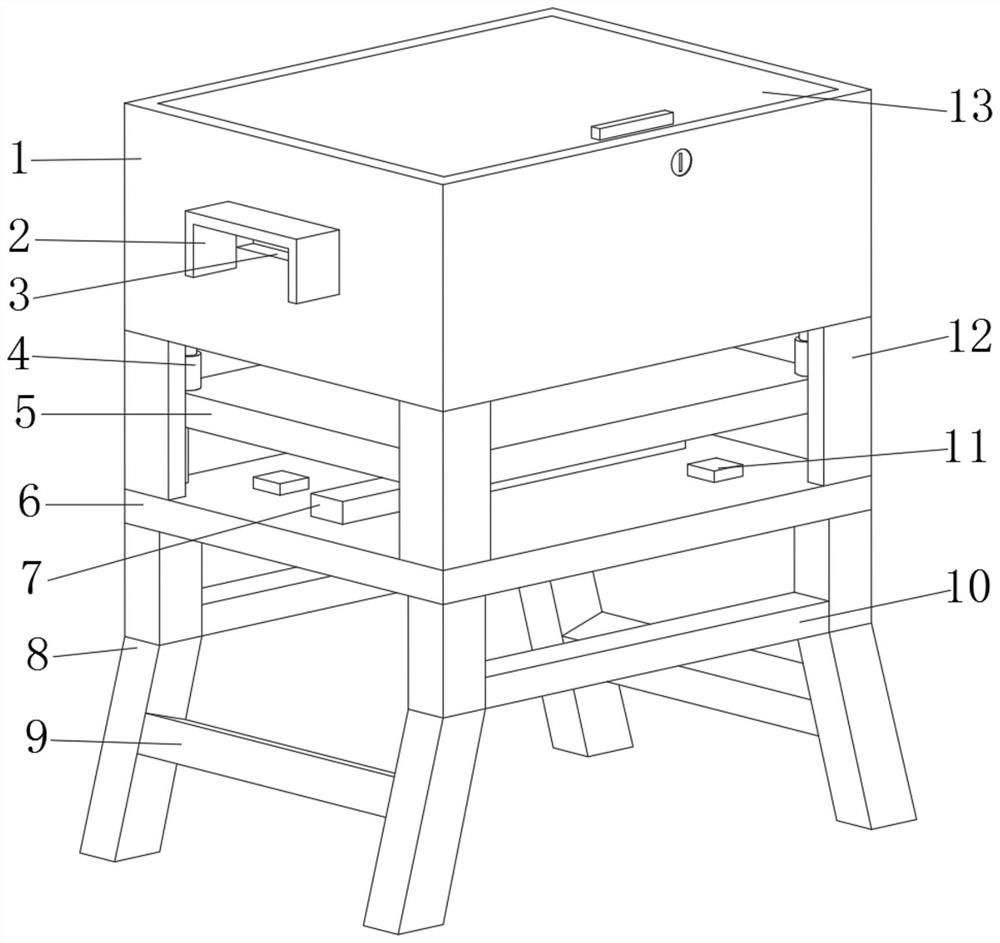
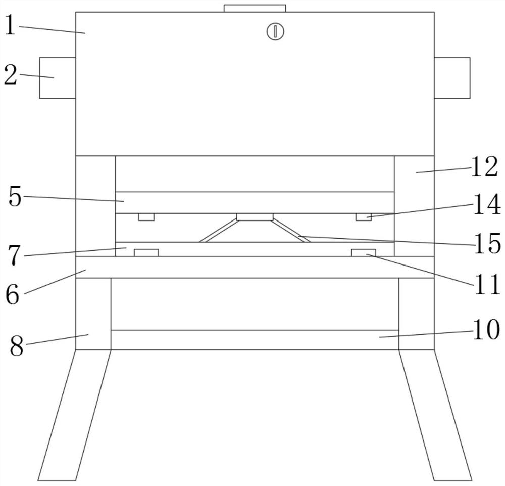
[0028] Refer Figure 1-5 A seismic transformer with a weight buffer function comprising a bottom plate 6 and a transformer cartridge body 1, and a support block 12 is fixed by a screw at the top outer wall of the bottom plate 6, and the transformer cartridge body 1 is fixed to the support block. At the top of 12, the bottom outer wall of the transformer box body 1 is fixed to the ferrous member 4 by the screw, and the bottom outer wall of the elastic member 4 is fixed by the screw 5, and the bottom outer wall of the weight block 5 is fixed by screws. The fixing plate, and the left and right sides of the fixed plate are rotated to the bottom of the connecting rod 15, and the top outer wall of the bottom plate 6 is fixed to the mounting block 7 by the screw, and the top outer wall of the mounting block 7 opens a slide, the left and right ends of the chute. There is a circular groove, and the bottom inner wall of the circular groove is fixedly connected to the spring 23, and one end o...

Embodiment 2

[0036] Refer Figure 5 A seismic transformer with a weight buffer function comprising a bottom plate 6 and a transformer cartridge body 1, and a support block 12 is fixed by a screw at the top outer wall of the bottom plate 6, and the transformer cartridge body 1 is fixed to the support block. At the top of 12, the bottom outer wall of the transformer box body 1 is fixed to the ferrous member 4 by the screw, and the bottom outer wall of the elastic member 4 is fixed by the screw 5, and the bottom outer wall of the weight block 5 is fixed by screws. The fixing plate, and the left and right sides of the fixed plate are rotated to the bottom of the connecting rod 15, and the top outer wall of the bottom plate 6 is fixed to the mounting block 7 by the screw, and the top outer wall of the mounting block 7 opens a slide, the left and right ends of the chute. There is a circular groove, and the bottom inner wall of the circular groove is fixedly connected to the spring 23, and one end of ...


PUM


Abstract

The invention belongs to the technical field of electric power tools, particularly relates to an anti-seismic transformer box with a counterweight buffer function. Aiming at the problem of poor anti-seismic effect of the transformer box, the anti-seismic transformer box of the scheme comprises a bottom plate and a transformer box body, supporting blocks are fixed at the four corners of the outer wall of the top of the bottom plate, and the transformer box body is fixed at the top ends of the supporting blocks; elastic pieces are fixed to the positions, close to the four corners, of the outer wall of the bottom of the transformer box body, balancing weights are fixed to the outer walls of the bottoms of the elastic pieces, and fixing plates are fixed to the outer walls of the bottoms of thebalancing weights; connecting rods are rotatably connected to the positions, close to the bottoms, of the left sides and the right sides of the fixing plates, mounting blocks are fixed to the outer wall of the top of the bottom plate, and a sliding groove is formed in the outer wall of the top of the mounting block. According to the present invention, when an earthquake occurs, the transformer box body shakes up and down and left and right, so that a balancing weight is driven to shake up and down, the balancing weight is subjected to the elastic force effect of the elastic piece so as to keep smaller movement, and the stability of the transformer box body is improved.

Description

Technical field [0001] The present invention relates to the field of electricity tools, in particular, to a seismic transformer with a weight buffer function. Background technique [0002] Transformer is a device that uses electromagnetic induction to change the AC voltage, and the primary component is the primary coil, the secondary coil, and the core (magnetic core). The main functions are: voltage transformation, current transform, impedance transformation, isolation, regulator (magnetic saturated transformer), etc. According to the purpose, it can be divided into: power transformer and special transformer (electric furnace change, rectification, power frequency test transformer, voltage regulator, mining change, audio transformer, intermediate frequency transformer, high frequency transformer, impact transformer, instrument transformer, electronic transformer , Reactors, transformers, etc.). Circuit symbols common T as the beginning of the number. Example: T01, T201, etc. [...

Claims


Application Information

Patent Timeline
Patent Type & Authority Applications(China)
IPC IPC(8): H01F27/02H01F27/06F16F15/04E04H15/58
CPCH01F27/02H01F27/06F16F15/04E04H15/58
Inventor 朱艳娟
Owner 浙江龙呈电力设备有限公司
Learn More