
Connector, adaptive connector and connector assembly

A connector assembly and connector technology, which is applied to parts, connections, and two-part connection devices of connecting devices, can solve problems such as increased product cost, large installation space, and increased product weight, and achieve improved locking strength, Effect of increased contact area and high mechanical performance

Pending Publication Date: 2021-03-12
CHINA AVIATION OPTICAL-ELECTRICAL TECH CO LTD
View PDF0 Cites 3 Cited by
  • Summary
  • Abstract
  • Description
  • Claims
  • Application Information

AI Technical Summary

Problems solved by technology

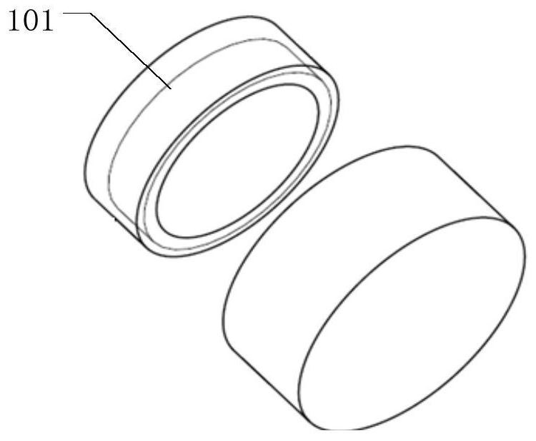
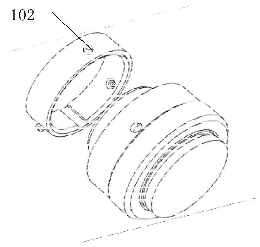
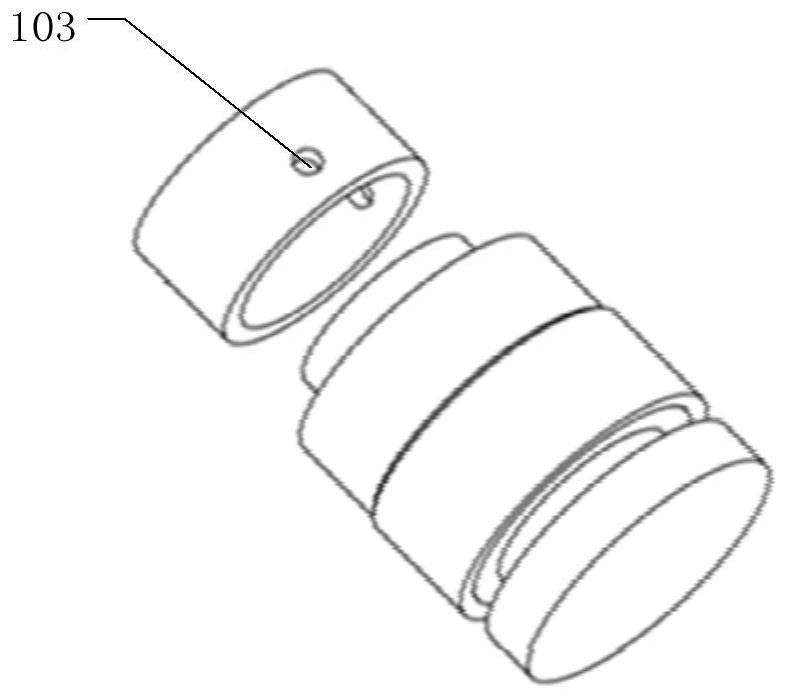
[0003] Thread 101 and bayonet ( figure 2 The shown staple 102 is matched with the corresponding staple hole) When the connectors of these two locking methods are used, a large installation space is required, so when designing the equipment, it is necessary to reserve a connector installation space on it, resulting in a large Space and cost are wasted, and these two locking forms cannot realize fast locking and separation of the connector, and it takes a long time for the construction personnel to install the connector when using it; the existing push-pull connector generally has two Type one, the first one: locking through the buckle structure, which requires a certain deformation capacity for locking the buckle, so to a certain extent, it limits the size of the locking structure and the mechanical properties of the connector. , especially in application scenarios with high tensile performance requirements, which cannot meet the requirements. The second type: locking by steel ball 103, the locking structure of steel ball can realize fast locking, but because the contact at the locking position is point contact, The locking mechanical strength is low. In order to improve the strength, the material of the steel ball locking and matching part needs high-strength materials. Therefore, metal is generally used in the prior art, and the wall thickness of the material at the locking position is increased at the same time. However, no matter whether high-strength materials are selected Either increasing the wall thickness will greatly increase the cost of the product, and increasing the wall thickness will also cause the product size to increase, which will lead to an increase in the installation size of the connector, an increase in the reserved position on the device, and an increase in product weight; another On the one hand, the processing of steel ball holes is relatively complicated, and can only be processed by machining, and cannot be processed by mold technology, and the cost is high. Therefore, the push-pull locking structure in the form of steel balls limits the miniaturization and cost reduction of products to a certain extent. development trend

Method used


Image

  • Connector, adaptive connector and connector assembly
  • Connector, adaptive connector and connector assembly
  • Connector, adaptive connector and connector assembly

Examples


Embodiment 2

[0036] Such as Figure 8 with Figure 9 As shown, the difference between this embodiment and Embodiment 1 is that the floating unit can also be a locking piece 4 integrally formed with the connector housing. The locking piece 4 is an elastic cantilever structure, and its front end is a movable end, which has a lock The locking protrusion 41 is adapted to the shape of the tight groove; during the mating process of the head seat, the housing of the adapter connector lifts up the locking piece, the front end of the locking piece lifts up and pushes the locking sleeve back, and the return spring compresses, Then, after the locking projection of the locking piece falls into the locking groove, the locking sleeve is reset under the action of the return spring and presses the locking piece to prevent its movable end from lifting, and at the same time, the two ends of the head seat are sealed by the sealing unit Achieving a seal. Since the locking piece and the locking groove are al...


PUM


Abstract

The invention provides a connector assembly. The connector assembly comprises a connector and an adaptive connector which are in plugging cooperation, the connector comprises a connector shell, the adaptive connector comprises an adaptive connector shell, and the connector shell is equipped with a floating unit which is arranged movably along the radial direction. The floating unit falls into a locking groove formed in the outer peripheral surface of the adaptive connector shell after the connector is inserted into the adaptive connector and is in axial stop fit with the locking groove, and atthe moment, the floating unit and the locking groove are in surface contact in the axial direction. Rapid push-and-pull locking can be realized, surface-to-surface contact between the floating unit and the locking groove during locking is ensured, the locking strength is improved, and the requirement of high mechanical performance of the connector is met; on the other hand, the locking structurecan be machined in a machining mode, meanwhile, a low-cost process can be used, and the cost is remarkably reduced.

Description

technical field [0001] The invention belongs to the technical field of connectors, in particular to a connector, an adapter connector and a connector assembly. Background technique [0002] Optical fiber communication technology is developing in the direction of high transmission rate and high bandwidth. Optical fiber connection technology has developed with the development of optical fiber communication technology. One of the most widely used basic optical passive devices in the application field. Low cost, easy operation, high reliability, and miniaturization are the development trends of optical fiber connectors in the future. There are generally three types of locking structures used in existing connectors, such as Figures 1 to 3 As shown: screw type, bayonet type, push-pull type, push-pull type locking structure is the most convenient structure to use at present, basically there are two types: buckle type and steel ball type. [0003] Thread 101 and bayonet ( figure...

Claims


Application Information

Patent Timeline
Patent Type & Authority Applications(China)
IPC IPC(8): G02B6/38H01R13/639H01R24/00
CPCG02B6/3807G02B6/3825G02B6/389H01R13/639H01R24/00
Inventor 陈明刘乃常王旭涛韩云钊杨帅杰赵晓鸣李卫可武学顺
Owner CHINA AVIATION OPTICAL-ELECTRICAL TECH CO LTD
Learn More