
Thermal treatment furnace

A technology of heat treatment furnace and furnace body, applied in heat treatment furnaces, heat treatment equipment, furnaces, etc., can solve the problems of poor mechanical stability of materials and restrict the development of aluminum alloy hot forming, and achieve the effect of ensuring uniformity

Active Publication Date: 2019-03-08
上海赛科利汽车模具技术应用有限公司
View PDF7 Cites 0 Cited by
  • Summary
  • Abstract
  • Description
  • Claims
  • Application Information

AI Technical Summary

Problems solved by technology

[0002] As the country's automobile power source gradually develops towards batteries, and the driving mileage of batteries has a great relationship with the weight of the vehicle itself, this requires lightweight automotive materials. At present, the lightweight of automotive components is gradually developing towards aluminum alloys. The development of existing domestic aluminum alloy heat treatment equipment is still in its infancy, there is no real aluminum alloy heat treatment equipment, and heat treatment is performed on the original box furnace, and the mechanical stability of the material after heat treatment is extremely poor, thus restricting Development of Domestic Aluminum Alloy Hot Forming

Method used


Image

  • Thermal treatment furnace
  • Thermal treatment furnace
  • Thermal treatment furnace

Examples


Embodiment Construction

[0030] The specific implementation manners of the present invention will be described in further detail below in conjunction with the accompanying drawings.

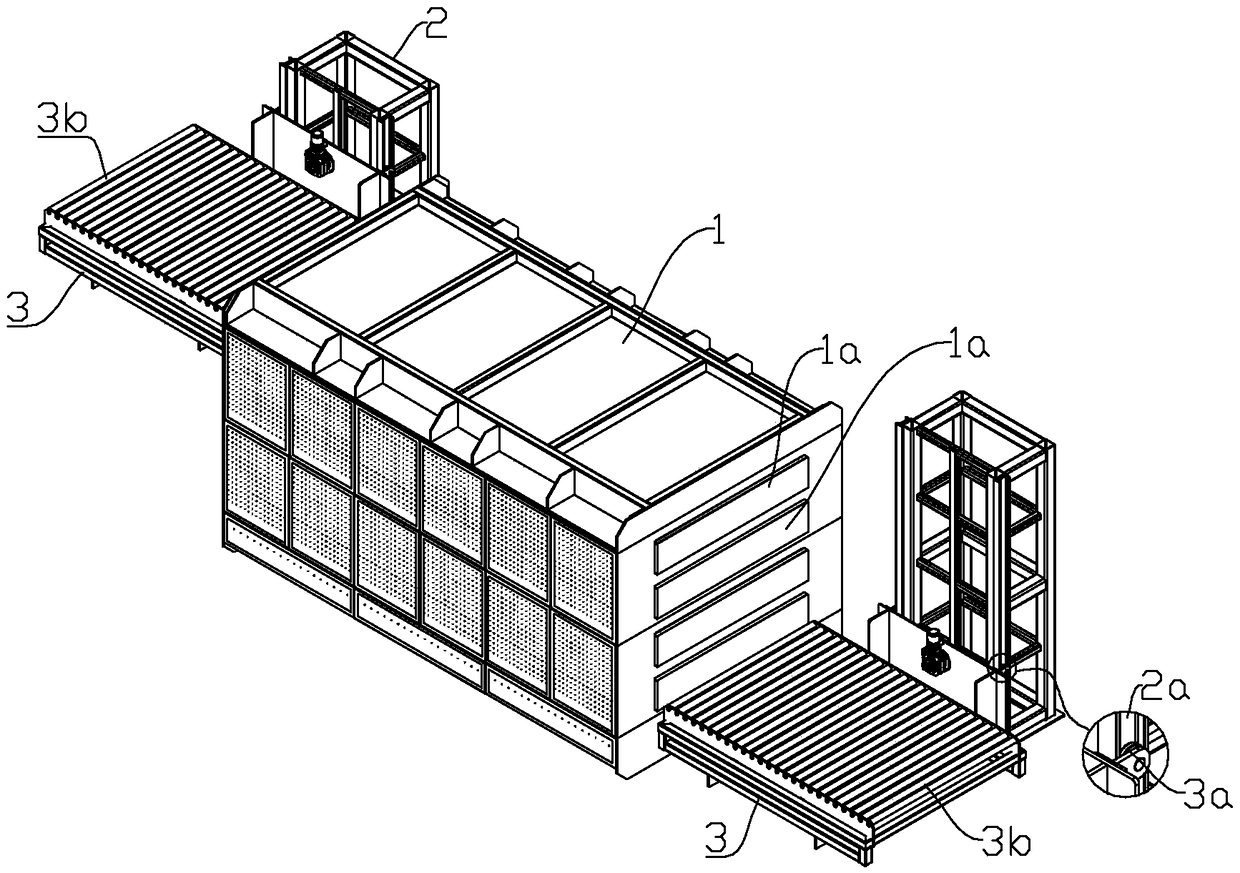
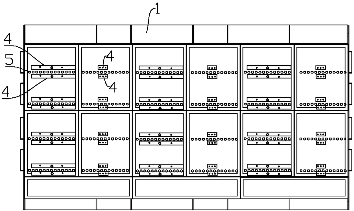
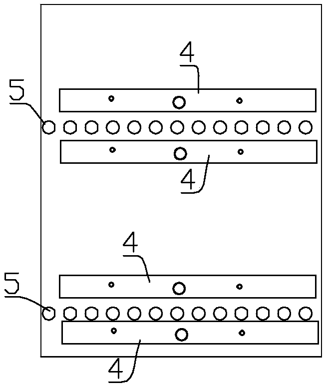
[0031] A heat treatment furnace, combined with figure 1 and figure 2 , the heat treatment furnace includes a furnace body 1, and a transfer roller 5 is arranged inside the furnace body 1; in order to improve heat treatment efficiency, the transfer roller 5 is distributed with multiple layers in the furnace body 1 in this embodiment; correspondingly, at the inlet and outlet ends of the furnace body 1 There are a plurality of furnace doors 1a corresponding to the number of layers of the conveying roller 5; the inlet and outlet ends of the furnace body 1 are respectively provided with a lifting platform 3 for feeding and discharging materials, and the side of the lifting platform 3 is slidingly connected to the lifting frame 2; The vertical chute 2a is arranged on both sides of the lifting frame 2, and the back of the lif...


PUM


Abstract

The invention belongs to the technical field of thermal treatment equipment, and particularly relates to a thermal treatment furnace. A transfer roll is arranged in a furnace body, and heating air flue assemblies are arranged above and below the transfer roll correspondingly and comprise outer boxes and inner boxes; the inner boxes are located in the outer boxes, inner air flues are formed in theinner boxes, and outer air flues are formed in spaces between the outer boxes and the inner boxes; an air inlet is formed in one end of each inner box and stretches out of the corresponding outer box,and the other end of each inner box is provided with an air outlet which is connected with a fan; the inner air flues and the outer air flues communicate through the fans, and heating elements are arranged in the inner boxes; and air discharging holes are formed in the side walls, facing the transfer roll, of the outer boxes. According to the thermal treatment furnace, a thermal air flue structure is adopted, and uniformity of the temperature in the furnace body is ensured.

Description

technical field [0001] The invention belongs to the technical field of heat treatment equipment, and in particular relates to a heat treatment furnace. Background technique [0002] As the country's automobile power source gradually develops towards the battery, and the driving mileage of the battery has a great relationship with the weight of the vehicle itself, this requires lightweight automotive materials. At present, the lightweight of automotive components is gradually developing in the direction of aluminum alloys. The development of existing domestic aluminum alloy heat treatment equipment is still in its infancy, there is no real aluminum alloy heat treatment equipment, and heat treatment is carried out on the original box furnace, and the mechanical stability of the material after heat treatment is extremely poor, thus restricting The development of domestic aluminum alloy thermoforming. Contents of the invention [0003] The object of the present invention is t...

Claims


Application Information

Patent Timeline
Patent Type & Authority Applications(China)
IPC IPC(8): C22F1/04C21D9/00
CPCC21D9/0006C22F1/04
Inventor 岑根生
Owner 上海赛科利汽车模具技术应用有限公司
Learn More