
Cell separation apparatus and cell separation method

A separation device and cell technology, applied in the field of cell separation, can solve the problems affecting the use safety of cell therapy products, loss of cell markers, tumorigenesis of stem cells, etc., and achieve high industrial utilization value, complete solid-liquid separation, and good separation effect. Effect

Pending Publication Date: 2021-03-09
TIANJIN DIAN ZHIXIN MEDICAL LAB
View PDF4 Cites 2 Cited by
  • Summary
  • Abstract
  • Description
  • Claims
  • Application Information

AI Technical Summary

Problems solved by technology

These systems use diaphragm pumps or centrifugal pumps as the power to pump the cell culture medium mixture, which suffers from the disadvantage of excessive shear force
Animal cells (especially human T cells or stem cells) are very sensitive to shear stress. Excessive shear stress may lead to tumorization of stem cells or loss of cell markers, which seriously affects the safety of cell therapy products.

Method used


Image

  • Cell separation apparatus and cell separation method
  • Cell separation apparatus and cell separation method
  • Cell separation apparatus and cell separation method

Examples


Embodiment 1

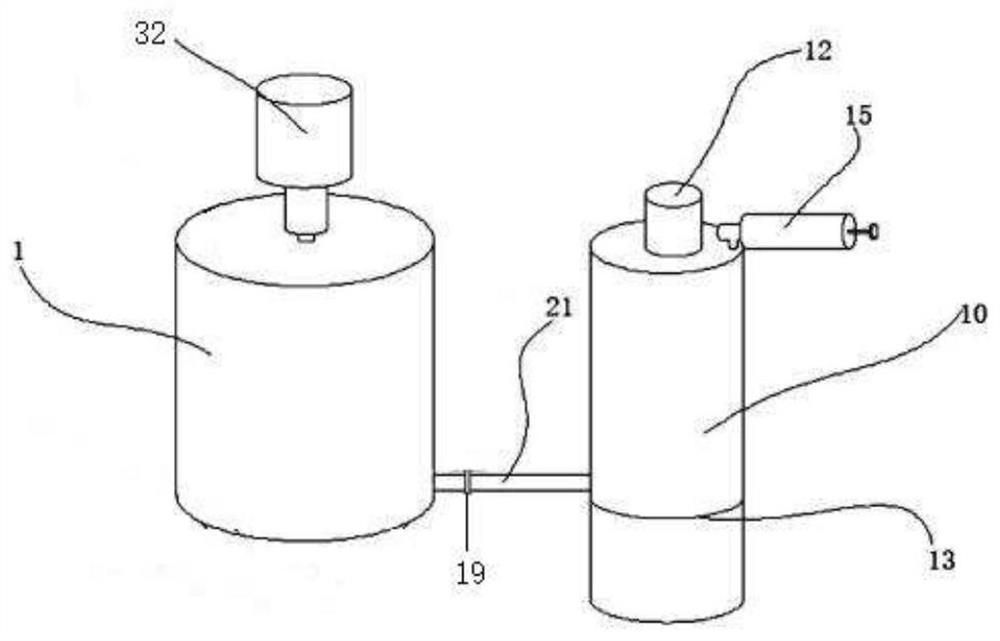
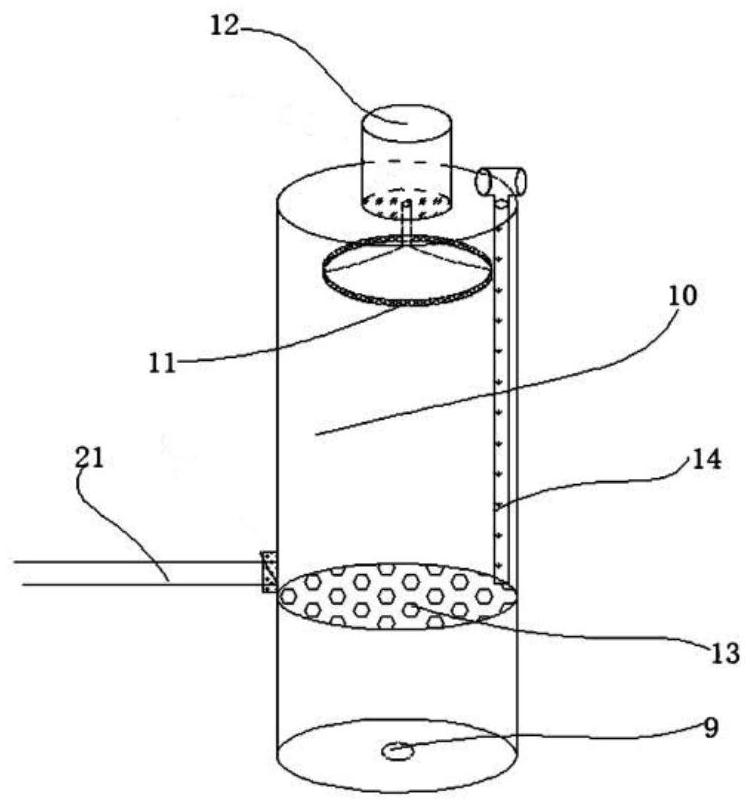
[0024] The cell separation device includes a stirring chamber, a connection device and a separation chamber, the stirring chamber is connected to the separation chamber through the connection device, and the connection device includes a connecting tube and the clamping device on the connection The channel valve on the pipe, the two ends of the connecting pipe extend into the stirring cavity and the separation cavity respectively, the channel valve includes a rotating shaft perpendicular to the connecting pipe, and a passageway is opened in the middle of the rotating shaft. The through hole matches the pipe setting of the connecting pipe, and the end of the rotating shaft is provided with a turning handle.

Embodiment 2

[0026] The cell separation device includes a stirring chamber, a connection device and a separation chamber, the stirring chamber is connected to the separation chamber through the connection device, and the connection device includes a connecting tube and the clamping device on the connection The channel valve on the pipe, the two ends of the connecting pipe extend into the stirring cavity and the separation cavity respectively, the channel valve includes a rotating shaft perpendicular to the connecting pipe, and a passageway is opened in the middle of the rotating shaft. The through hole matches the pipe setting of the connecting pipe, and the end of the rotating shaft is provided with a turning handle.

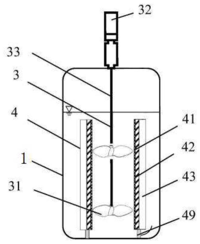
[0027] The stirring chamber includes one or more paddles, which are located radially inside the cell separation assembly and can rotate around a rotation axis to drive the mixture to flow tangentially along the filter membrane.

Embodiment 3

[0029] The cell separation device includes a stirring chamber, a connection device and a separation chamber, the stirring chamber is connected to the separation chamber through the connection device, and the connection device includes a connecting tube and the clamping device on the connection The channel valve on the pipe, the two ends of the connecting pipe extend into the stirring cavity and the separation cavity respectively, the channel valve includes a rotating shaft perpendicular to the connecting pipe, and a passageway is opened in the middle of the rotating shaft. The through hole matches the pipe setting of the connecting pipe, and the end of the rotating shaft is provided with a turning handle.

[0030] The stirring chamber includes one or more paddles, which are located radially inside the cell separation assembly and can rotate around a rotation axis to drive the mixture to flow tangentially along the filter membrane.

[0031] The stirring chamber includes a cell ...


PUM


Abstract

The invention provides a cell separation apparatus. The cell separation apparatus comprises a stirring cavity, a connecting apparatus and a separation cavity, wherein the stirring cavity is connectedwith the separation cavity through the connecting apparatus, the connecting apparatus comprises a connecting pipe and a channel valve clamped on the connecting pipe, two ends of the connecting pipe extend into the stirring cavity and the separation cavity respectively, the channel valve comprises a rotating shaft perpendicular to the connecting pipe, a through hole is formed in the middle of the rotating shaft, the through hole is matched with a pipeline of the connecting pipe, and a rotating handle is arranged at the end of the rotating shaft. The beneficial effects are as follows: the adipose-derived stem cell separation apparatus provided by the invention has the advantages of good separation effect, convenience in sampling, thorough solid-liquid separation and difficulty in bacterium generation. Therefore, the cell separation apparatus effectively overcomes various defects in the prior art and has high industrial utilization value.

Description

technical field [0001] The invention relates to the field of cell separation, in particular to a cell separation device and a cell separation method. Background technique [0002] In animal cell expansion, more and more processes involve the separation of cells from culture medium or other liquids, such as perfusion culture, medium exchange or cell washing. Traditional separation equipment includes ATF system and TFF system, etc. These systems use diaphragm pumps or centrifugal pumps as power to pump the mixture of cells and medium into hollow fiber columns, and use the fiber pores of the hollow fiber columns to separate cells and medium. These systems use diaphragm pumps or centrifugal pumps as the power to pump the cell culture medium mixture, which has the disadvantage of high shear force. Animal cells (especially human T cells or stem cells) are very sensitive to shear stress. Excessive shear stress may lead to tumorization of stem cells or loss of cell markers, seriou...

Claims


Application Information

Patent Timeline
IPC IPC(8): C12M1/26C12M1/12C12M1/02C12M1/00
CPCC12M23/48C12M27/02C12M29/06C12M33/04C12M33/14C12M37/04C12M47/04
Inventor 管学丰
Owner TIANJIN DIAN ZHIXIN MEDICAL LAB
Learn More