
Shield cutter head suitable for soft and hard composite stratum and tunneling method

A shield cutter head, soft and hard composite technology, applied in the direction of earth drilling, mining equipment, tunnels, etc., can solve the problems that the dregs cannot be guaranteed to enter the soil bin smoothly, the hob is not considered, and the impact force is large, so as to avoid Severe wear, improve rock breaking efficiency, and prevent string grinding

Pending Publication Date: 2021-03-02
THE 3RD ENG CO LTD OF CHINA RAILWAY 18TH BUREAU GRP +1
View PDF1 Cites 5 Cited by
  • Summary
  • Abstract
  • Description
  • Claims
  • Application Information

AI Technical Summary

Problems solved by technology

"A shield cutter head structure for soft-hard heterogeneous inter-invasion composite rock formations" did not consider the influence of hob starting torque on shield tunneling efficiency, that is, when the starting torque is large, the conventional hob When the formation enters the soft soil (gravel sand) formation, due to the insufficient friction provided, the hob is difficult to rotate, which induces string grinding; and when the starting torque is adjusted too small, the overall stiffness of the hob decreases. In hard rock formation and soft-hard composite interface The impact force at the variable stiffness position is large, which may easily cause the hob to loosen or even be damaged
In addition, the cutterhead opening ratio in this patent is 20%-30%. When the excavation stratum is argillaceous siltstone stratum with high clay content, it cannot guarantee that the muck will enter the soil bin smoothly, which will induce mud cake formation on the cutterhead.

Method used


Image

  • Shield cutter head suitable for soft and hard composite stratum and tunneling method
  • Shield cutter head suitable for soft and hard composite stratum and tunneling method
  • Shield cutter head suitable for soft and hard composite stratum and tunneling method

Examples


Embodiment Construction

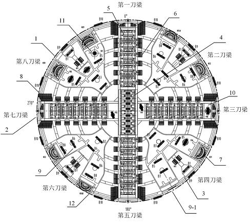
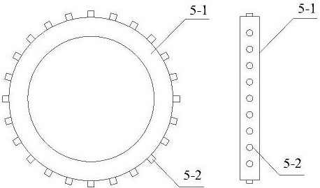
[0032] Such as figure 1 and figure 2As shown, this embodiment is a shield cutter head suitable for soft-hard composite formations, mainly including a shield cutter head 1, a cross-shaped main knife beam 2, an auxiliary knife beam 3, a center tooth knife 4, a front hob 5, an inlay Tooth hob blade 5-1, alloy column teeth 5-2, cutter 6, edge hob 7, edge scraper 8, fixed tooth cutter 9, super digging tooth cutter 9-1, foam nozzle 10, wear detection knife 11, Wear-resistant steel plate 12 and other necessary components not listed.

[0033] The main working principle of a shield cutter head suitable for soft-hard composite formations in this embodiment is as follows:

[0034] The main load-bearing structure of the shield cutter head 1 is formed by the cross-shaped main knife beam 2 and the auxiliary knife beam 3 .

[0035] Eight central toothed cutters 4 with a cutter height of 175mm are installed at the center of the cross-shaped main cutter beam 1, and the cutter spacing is se...


PUM


Abstract

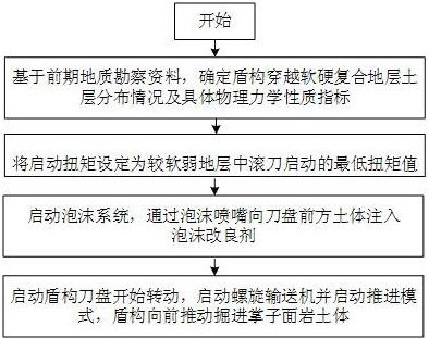
The invention provides a shield cutter head suitable for a soft and hard composite stratum and a tunneling method. The cutter head comprises a shield cutter head body (1), a cross-shaped main cutter beam (2), an auxiliary cutter beam (3), a center serrated cutter (4), a front hob (5), a cutter (6), an edge hob (7), an edge scraper (8), a fixed serrated cutter (9), a foam nozzle (10), a wear detection cutter (11), a wear-resistant steel plate (12) and other components. The cross-shaped main cutter beam is composed of a first cutter beam, a third cutter beam, a fifth cutter beam and a seventh cutter beam, and the auxiliary cutter beam is composed of a second cutter beam, a fourth cutter beam, a sixth cutter beam and an eighth cutter beam. The method comprises the steps of determining the starting torque of the hobs, selecting and setting the starting torque of the hobs as the starting torque of the hobs of the soft soil stratum, starting a foam system to spray a foam modifier, and pushing a tunneling face rock-soil body forwards by a shield. The opening rate of the cutter head reaches 43%, the cutter head is particularly suitable for tunneling of a typical gravel-argillaceous siltstone composite stratum, and the risk of mud pasting of the cutter head is reduced.

Description

technical field [0001] The invention relates to a shield cutterhead and an excavation method suitable for soft and hard composite strata, belonging to the technical field of excavation machinery. Background technique [0002] With the rapid development of my country's economy, the demand for urban underground space development is increasing, and a large number of urban tunnel projects have emerged. Among them, the shield tunneling method is more and more widely used in urban tunnel excavation because of its high construction efficiency (integrated construction of excavation and support), good tunnel formation, and low impact on the surrounding environment. However, when encountering a soft-hard composite formation (such as the typical upper-soft-lower-hard composite formation of the upper sand layer-lower argillaceous siltstone in Nanchang), many problems are often induced due to the huge difference in the formation conditions. The typical ones are: when When the disc-shape...

Claims


Application Information

Patent Timeline
Patent Type & Authority Applications(China)
IPC IPC(8): E21D9/08E21D9/06
CPCE21D9/08E21D9/0678
Inventor 赵广资徐琳琳齐跃军张明伟蒋亚龙朱碧堂罗文俊周双喜
Owner THE 3RD ENG CO LTD OF CHINA RAILWAY 18TH BUREAU GRP
Learn More