
Wave-dissipating block

a technology of wave dissipation block and wave, which is applied in the direction of piers, machines/engines, groynes, etc., can solve the problems of body, inability to efficiently generate electric power, and ineffective rotation of turbine fans (b>941/b>), and achieve the effect of efficient utilization of the kinetic energy contained in waves

Inactive Publication Date: 2008-07-24
LIOU BAI CHIENG +3
View PDF4 Cites 20 Cited by
  • Summary
  • Abstract
  • Description
  • Claims
  • Application Information

AI Technical Summary

Benefits of technology

[0023]The primary objective of the present invention is to provide a wave-dissipating block mitigate the aforementioned problems of the conventional apparatuses to efficiently utilize kinetic energy contained in waves.
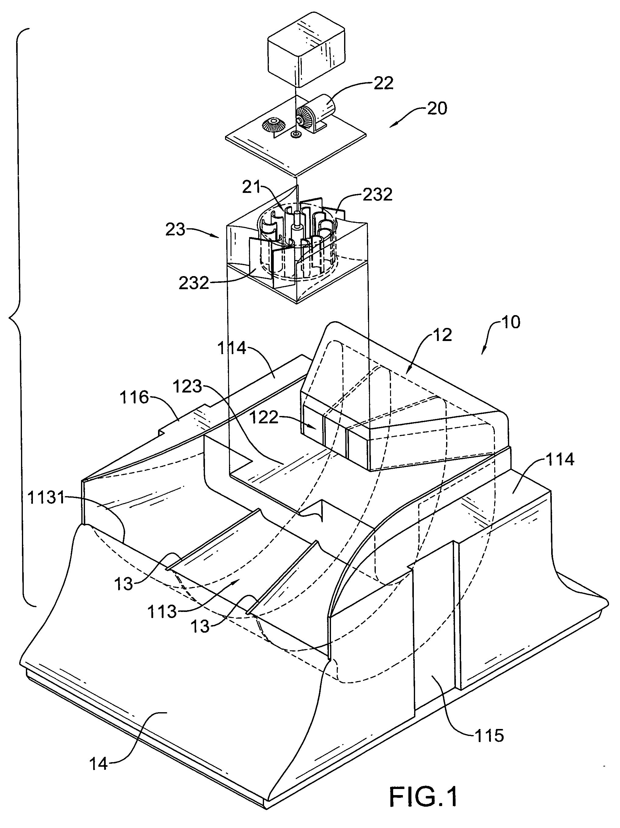
[0024]The wave-dissipating block has a body and a turbine generator assembly. The body has a front, a top, an airway and an overhang. The airway is formed in the body, is substantially J-shape and has a curved part and a longitudinal part. The curved part has an opening communicating with the front of the body and substantially facing upward. Thus, waves are easy to pour into the airway though the opening facing upward and avoid to be blocked or dissipated by other component of the body. So, the waves can directly pour into the airway with minimized loss of kinetic energy to forms a higher water column in the longitudinal part of the airway. When wave crests and wave troughs consecutively arrive in the opening, the water column rises or falls in the longitudinal part of the airway, air is respectively sucked into or pushed out of the airway.
[0026]The turbine generator assembly has a housing, a turbine fan and a generator. The housing is mounted on the overhang and has an air channel. The air channel is formed through the housing and communicates with the air window in the overhang for air to pass through to be sucked or pushed out of the airway. The turbine fan is mounted rotatably in air channel and is rotated by the air passing through the air channel. The generator is connected to and driven by the turbine fan to generate electric power. Because waves can pour into the airway with least loss of kinetic energy, the water column in the airway forms an enough drop height between a uppermost point and a lowest point to effectively suck or push air to passing through the air channel. Thus, the turbinate fan can be effectively rotated and the generator can efficiently generate electric power at all times.

Problems solved by technology

Thus, a drop height of the waves in the minor air chambers (95, 96) is inefficient so that the turbine fan (941) can not be effectively rotated.
Accordingly, the generator (942) is unable to efficiently generate electric power.
Additionally, the body (90) made of metal frequently contacts with seawater and is easily rusted.
Accordingly, air in the air chamber (811) and the body (80) can not be effectively forced to rotate the turbine fan (821) to make the generator (822) inefficient to generate electric power.
Consequently, air in the air chamber (702) can not be effectively push upward and the generator (712) is unable to efficiently generating electric power.

Method used


Image

  • Wave-dissipating block
  • Wave-dissipating block
  • Wave-dissipating block

Examples


Embodiment Construction

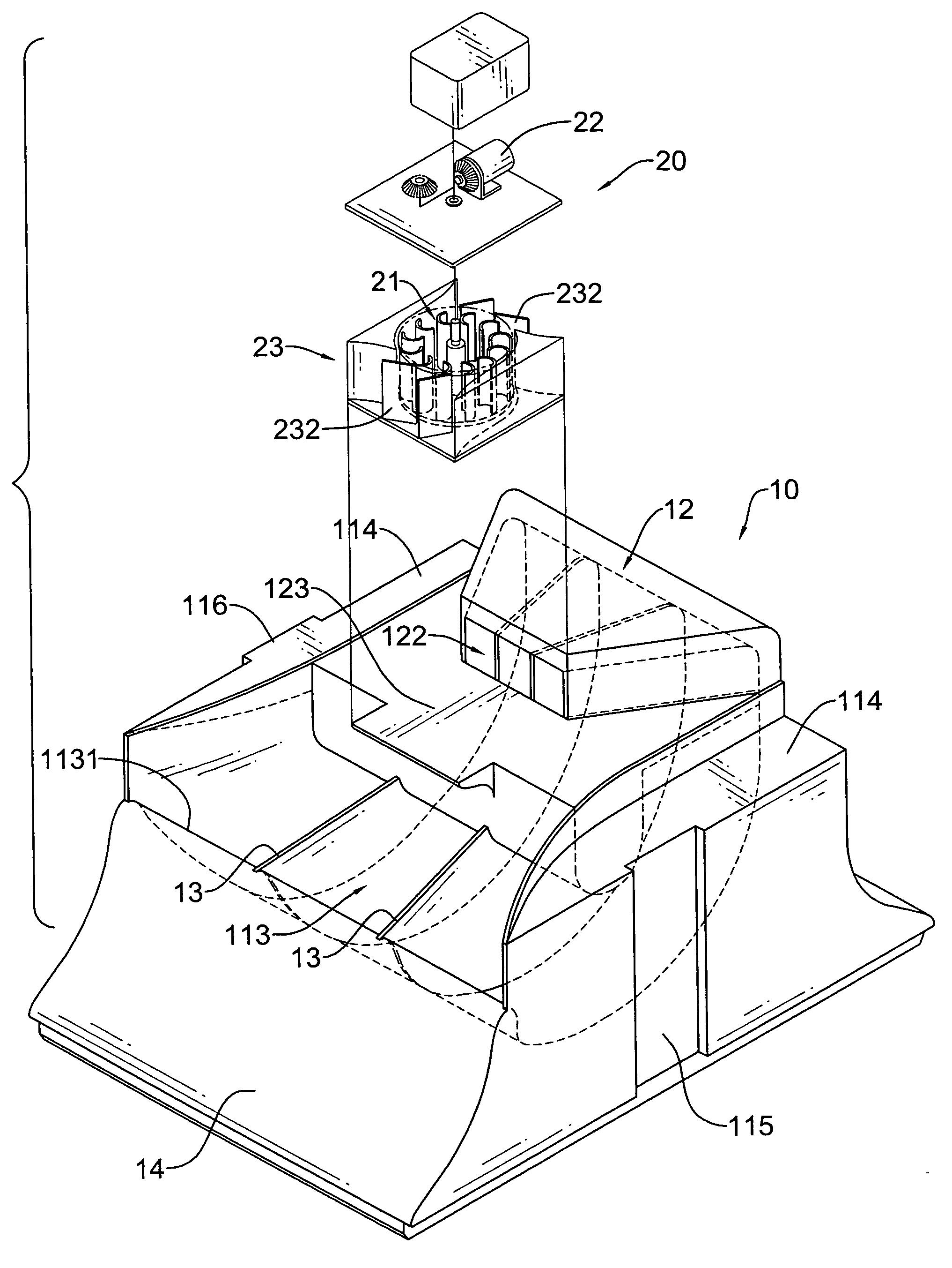
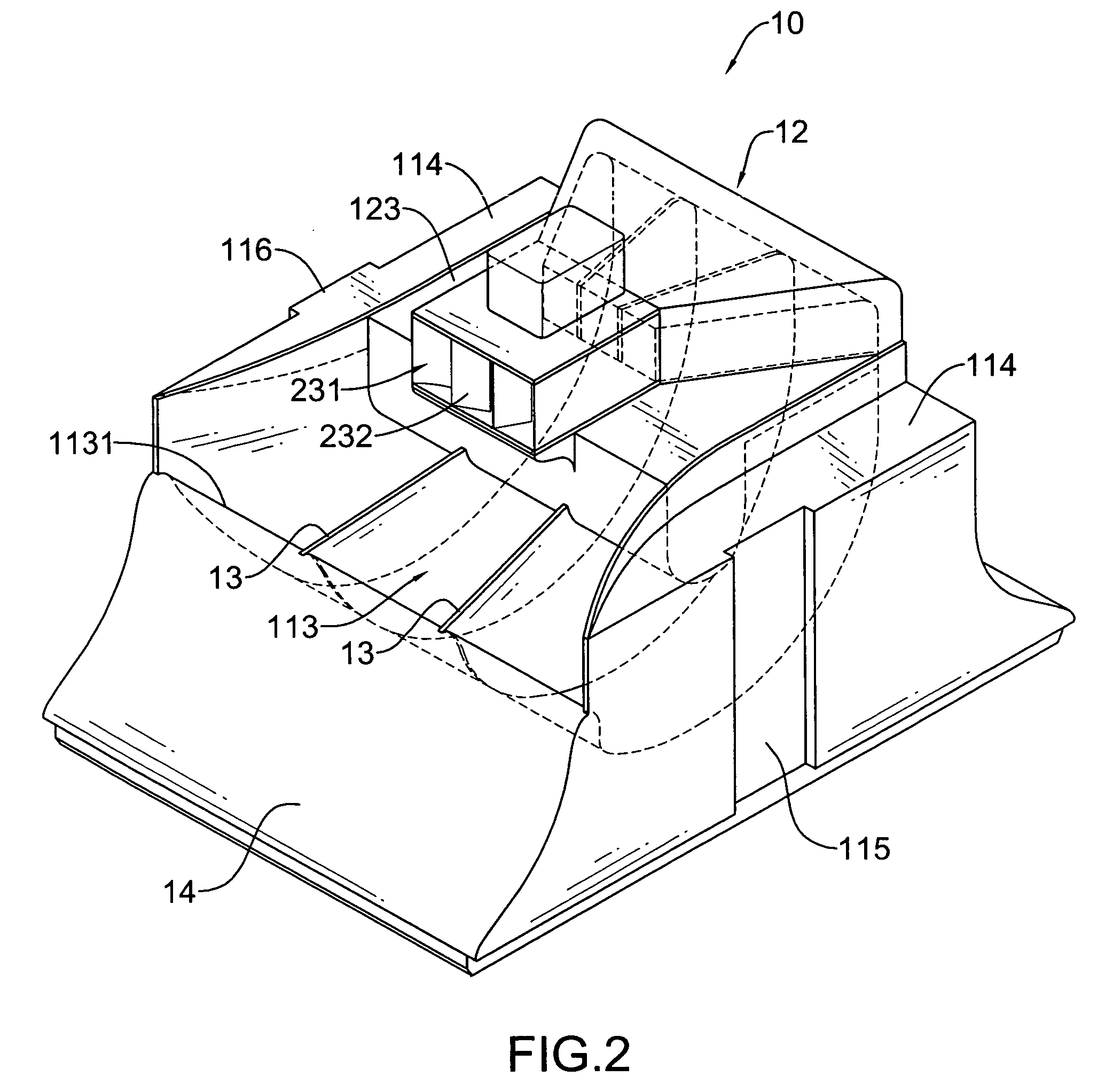
[0039]With reference to FIGS. 1 and 2, a wave-dissipating block in accordance with the present invention comprises a body (10) and a turbine generator assembly (20).

[0040]With further reference to FIGS. 3 and 4, the body (10) is made of concrete and has a front, a rear, a top, a bottom, two sides, an airway (11), an overhang (12), multiple partition panels (13), a guide surface (14), two spillways (114), a connecting recess (115) and a connecting protrusion (116). The body (10) is made of concrete to prevent from being rusted by seawater.

[0041]The airway (11) is formed in the body (10), is substantially J-shape and has two side walls, a curved part (111) and a longitudinal part (112). The curved part (111) has a proximal end, a distal end and an opening (113) and may be gradually narrowed toward the proximal end of the curved part (111). Thus, waves can be gradually gathered together when passing through the curved part (111). The opening (113) is formed at the distal end of the cur...


PUM


Abstract

A wave-dissipating block has a body and a turbine generator assembly. The body has an airway and an overhang. The airway is formed in the body, is substantially J-shape and has an opening communicating with a front of the body and substantially facing upward. The overhang hangs over the airway and has an air window formed in the overhang and communicating with the airway. The turbine generator assembly has a housing mounted on the overhang and has an air channel communicating with the air window, a turbine fan mounted in the air channel and a generator connected to the turbinate fan. Waves can directly pour into the airway with minimized loss of kinetic energy and forms a water column in the airway to effectively suck or push air to passing through the air channel to rotate the turbinate fan to drive the generator to efficiently generate electric power.

Description

BACKGROUND OF THE INVENTION[0001]1. Field of the Invention[0002]The present invention relates to a wave-dissipating block, and more particularly to a wave-dissipating block for constructing a breakwater and efficiently converting wave energy into electric power.[0003]2. Description of Related Art[0004]Enormous energy is contained in the ocean in types of ocean currents, tides and waves, so how to efficiently utilize the energy contained in the ocean is an important subject. Currently, there are several different types of apparatus have been developed to convert potential kinetic energy contained in the waves into electric power.[0005]With reference to FIGS. 8 and 9, a conventional apparatus that utilizes waves for generating electric power is equipped in an offshore ship and has a body (90). The body (90) is made of metal, is hollow and has an upper component, a lower component, an air chamber, an inlet channel (91), an outlet channel (92) and an activating chamber (93) and has a tu...

Claims


Application Information

Patent Timeline
Patent Type & Authority Applications(United States)
IPC IPC(8): E02B3/06
CPCE02B3/06F03B13/142Y02E10/38F03B13/24Y02E10/32F03B13/148Y02E10/30Y02A10/11
Inventor LIOU, BAI-CHIENG
Owner LIOU BAI CHIENG
Learn More