
Control method and system for SCR denitration system of all-working-condition power station

A control method and technology of all working conditions, applied in separation methods, chemical instruments and methods, genetic laws, etc., can solve problems such as affecting the safe operation of units, ammonia escape, and difficulty in obtaining control effects.

Pending Publication Date: 2021-02-26
NORTH CHINA ELECTRIC POWER UNIV (BAODING) +1
View PDF0 Cites 6 Cited by
  • Summary
  • Abstract
  • Description
  • Claims
  • Application Information

AI Technical Summary

Problems solved by technology

SCR denitrification is currently the mainstream flue gas denitrification technology, and its reaction is a complex physical and chemical process. More ammonia injection can reduce NO x emissions, but it will increase economic costs and lead to increased ammonia slip, affecting the safe operation of the unit
[0003] At present, the SCR control system applied in the field is mainly divided into two types, one is the fixed molar ratio control method, which is open-loop control and cannot meet the ultra-low emission requirements; the other is the fixed outlet NO x Concentration control method, at present, the cascade PID control system is mostly used on site, and its parameters are adjusted according to the characteristics of the reactor under the design (rated) working condition. When the working condition of the unit changes greatly, if the SCR system cannot be effectively controlled control, it will lead to low denitrification efficiency or serious ammonia escape phenomenon, it is difficult to achieve optimal control, which is extremely unfavorable to the economic and environmental protection operation of thermal power plants
Therefore, it is often difficult to achieve better control effects by using open-loop control and cascaded PID control methods.

Method used


Image

  • Control method and system for SCR denitration system of all-working-condition power station
  • Control method and system for SCR denitration system of all-working-condition power station
  • Control method and system for SCR denitration system of all-working-condition power station

Examples


Embodiment Construction

[0067]The purpose of the present invention is to provide a control method and system for the SCR denitrification system of a full-condition power station, so as to realize the optimized control of the denitrification system, and realize the economic operation of the unit while ensuring the emission standard.

[0068]In order to make the above-mentioned objects, features and advantages of the present invention more obvious and understandable, the invention will be further described in detail below with reference to the accompanying drawings and specific embodiments.

[0069]It should be noted that the terms "including" and "having" in the embodiments of the present invention and the drawings and any variations thereof are intended to cover non-exclusive inclusions. For example, a process, method, system, product, or device that includes a series of steps or units is not limited to the listed steps or units, but optionally includes unlisted steps or units, or optionally also includes Other ...


PUM


Abstract

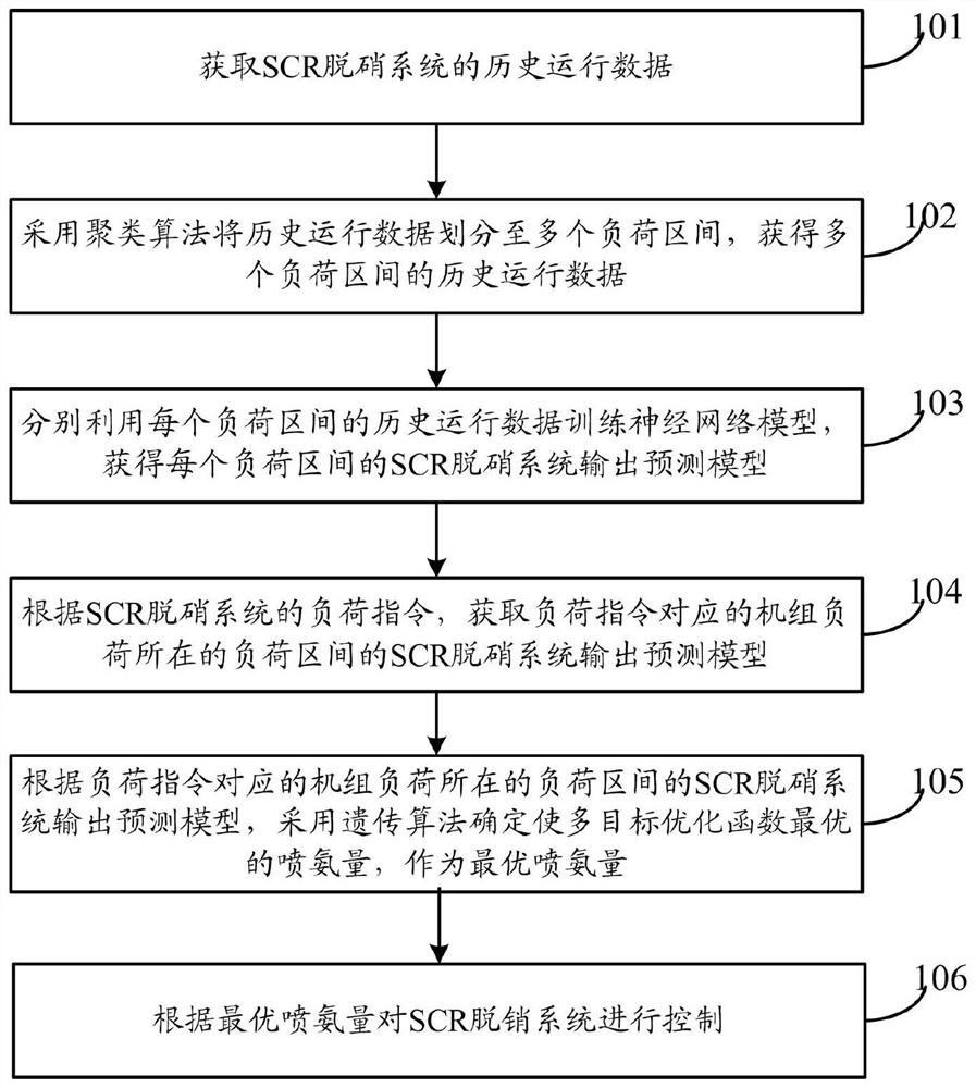
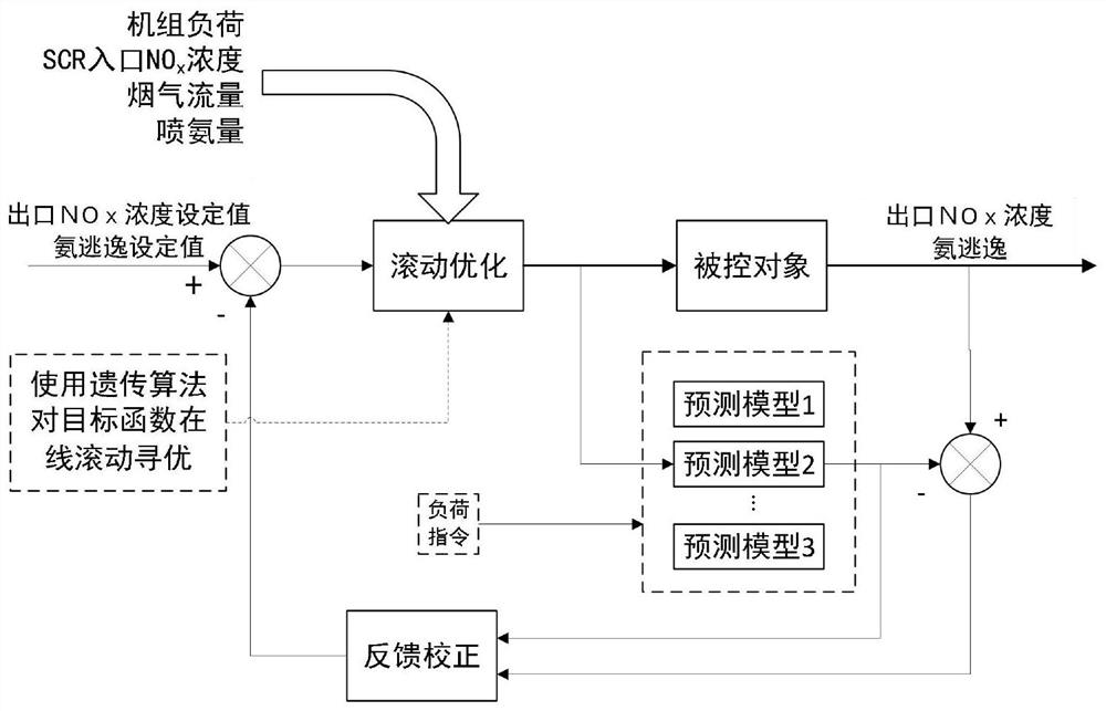
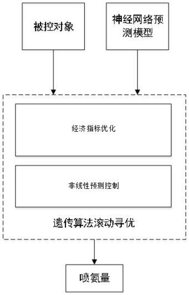
The invention discloses a control method and system for an SCR denitration system of an all-working-condition power station, and the control method comprises the steps of adding denitration cost intoan optimization objective function, employing a prediction control structure, carrying out the model building and control quantity optimization through combining a neural network and a genetic algorithm, and achieving the optimization control of ammonia spraying quantity. According to the invention, the future change trend of the NOx concentration at the outlet of the SCR reactor is predicted by constructing the neural network model, the ammonia injection flow of the SCR denitration system is determined by adopting genetic algorithm optimization, and the valve opening degree of the ammonia injection valve is adjusted, so that the method can better overcome the defects of large inertia and large delay of the SCR denitration system, the response speed of ammonia spraying amount control to unit load changes is increased, and the dynamic adjustment quality of the SCR denitration system is improved.

Description

Technical field[0001]The invention relates to the technical field of optimized control for coal-fired power stations, and in particular to a control method and system for an SCR denitrification system in a full-condition power station.Background technique[0002]In the process of energy structure transformation, the large-scale integration of new energy power into the grid puts forward operational flexibility requirements for coal-fired units. The rapid and deep load change means that the operating conditions of the unit change rapidly in a wide range, and the changes in the operating conditions of the boiler will cause the NO produced by combustionxIncreased volatility, which undoubtedly increased the unit’s realization of NOxThe difficulty of ultra-low emissions. SCR (Selective Catalytic Reduction)-Selective Catalytic Reduction is currently the most mature and widely used flue gas denitration technology in the world. SCR uses a reducing agent NH under the action of a catalyst3Wait t...

Claims


Application Information

Patent Timeline
IPC IPC(8): G06K9/62G06N3/04G06N3/12B01D53/86B01D53/56
CPCG06N3/126B01D53/8631G06N3/045G06F18/23G06F18/214
Inventor 杨婷婷白杨吕游张文广王坤
Owner NORTH CHINA ELECTRIC POWER UNIV (BAODING)
Learn More