Multifunctional spray pipe of snow blowing vehicle

A multi-functional, snow blower technology, which is applied in snow surface cleaning, construction, cleaning methods, etc., can solve the problems of fixed nozzle design, low snow removal efficiency, and no way to adjust nozzle holes in different road environments, so as to maintain stability, The effect of changing the flow rate

Active Publication Date: 2021-02-26
无锡柏鹏科技有限公司
View PDF7 Cites 1 Cited by
  • Summary
  • Abstract
  • Description
  • Claims
  • Application Information

AI Technical Summary

Problems solved by technology

[0004] Based on the multifunctional nozzle of the existing snow blower, the relative design of the nozzle of the existing snow blower is relatively fixed, there is no way to adjust the nozzle holes for different road environments, and the technical problems of low snow removal efficiency, the present invention proposes a snow blower multifunctional nozzle

Method used


Image

  • Multifunctional spray pipe of snow blowing vehicle
  • Multifunctional spray pipe of snow blowing vehicle
  • Multifunctional spray pipe of snow blowing vehicle

Examples


Embodiment 1

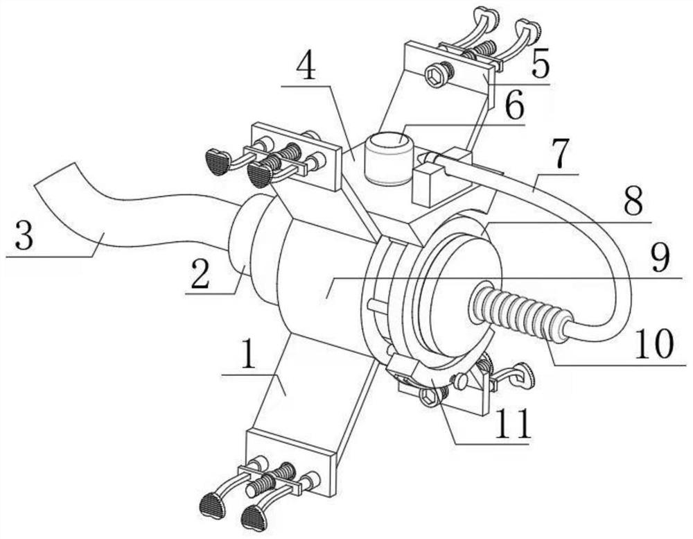
[0028] refer to Figure 1-5 , a multifunctional nozzle of a snow blower, comprising a main body frame 9, an annular chute is formed on the inner wall of the circumference of the main body frame 9, the inner wall of the annular chute is fixedly connected with an annular slide rail, and the inner wall of the annular slide rail is slidably connected with etc. The slider 18 distributed at a distance, the outer wall of one side of the slider 18 is fixedly connected with the same main body tube 14, one end of the main body tube 14 is fixedly connected with a fixed rod equidistantly distributed, and one end of the fixed rod is fixedly connected with the same ring frame 8. The ring frame 8 is slidingly socketed on the outer wall of the main body tube 14 near one end, and the inner wall of the main body tube 14 near one end is provided with leak holes 15 distributed equidistantly. The leak holes 15 communicate with the inside of the ring frame 8, and the ring frame One side outer wall ...

Embodiment 2

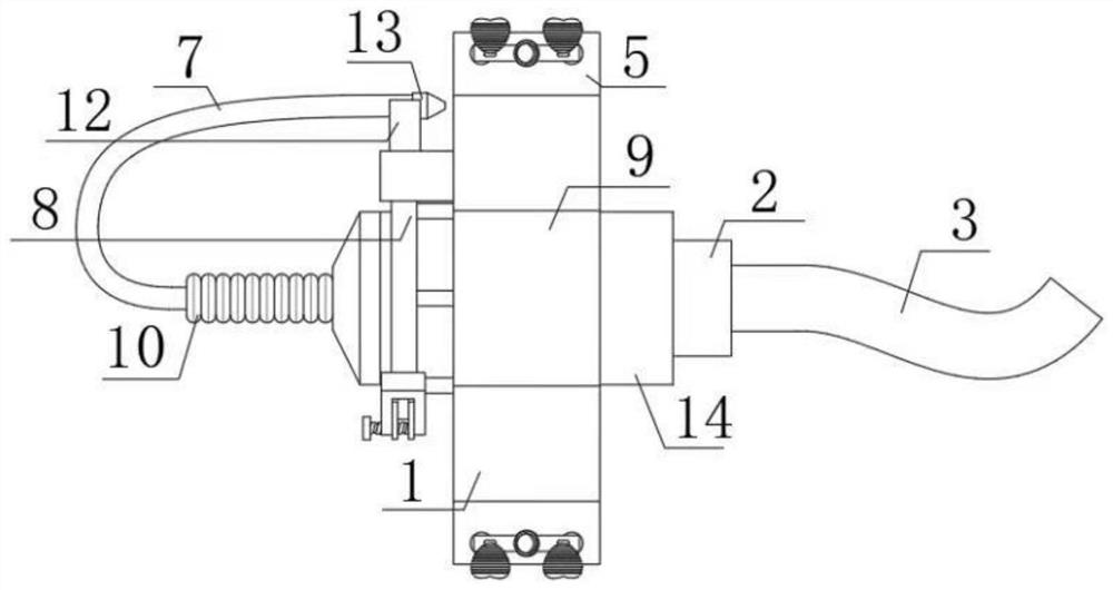
[0038] refer to Figure 6 , a multifunctional nozzle of a snow blower, comprising a main body frame 9, an annular chute is formed on the inner wall of the circumference of the main body frame 9, the inner wall of the annular chute is fixedly connected with an annular slide rail, and the inner wall of the annular slide rail is slidably connected with etc. The slider 18 distributed at a distance, the outer wall of one side of the slider 18 is fixedly connected with the same main body tube 14, one end of the main body tube 14 is fixedly connected with a fixed rod equidistantly distributed, and one end of the fixed rod is fixedly connected with the same ring frame 8. The ring frame 8 is slidingly socketed on the outer wall of the main body tube 14 near one end, and the inner wall of the main body tube 14 near one end is provided with leak holes 15 distributed equidistantly. The leak holes 15 communicate with the inside of the ring frame 8, and the ring frame One side outer wall of...


PUM


Abstract

The invention discloses a multifunctional spray pipe of a snow blowing vehicle, and provides the following scheme to solve the problems that an existing spray pipe of the snow blowing vehicle is relatively fixed in design, spray holes cannot be adjusted according to different road environments, and snow removing efficiency is low. According to the technical scheme, the spray pipe comprises a mainbody frame, and an annular sliding groove is formed in the circumferential inner wall of the main body frame; an annular sliding rail is fixedly connected to the inner wall of the annular sliding groove, sliding blocks distributed at equal intervals are slidably connected to the inner wall of the annular sliding rail, the same main body pipe is fixedly connected to the outer wall of one side of each sliding block, and fixing rods distributed at equal intervals are fixedly connected to one end of the main body pipe; one ends of the fixing rods are fixedly connected with the same annular frame,and the outer wall, close to one end, of the main pipe is sleeved with the annular frame in a sliding mode. The distance between the two sliding connection clamping plates on the inner wall of the spraying hole can be adjusted through the knob and the adjusting bolt, so that the spraying inner diameter of the spraying hole is changed, and the flow speed of hot air sprayed by the spraying hole is effectively changed.

Description

technical field [0001] The invention relates to the technical field of road snow removal facilities, in particular to a multifunctional nozzle of a snow blower. Background technique [0002] At present, road snow removal facilities refer to machinery and engineering equipment that remove snow on roads in winter and maintain traffic safety. Snow plows are often used on roads with large traffic volumes, which are divided into: snow plow type, which is connected by the front end of a tractor, bulldozer or truck to drive different types of scrapers, and has two types of tires and crawlers. Its advantage is the flexible use of road construction machinery, but its disadvantage is that it cannot clear the residual snow and requires the cooperation of manpower. Rotary type, there is a rotating wheel at the front of the machine, which stirs the snow into it and passes it through the snow blower, throwing the snow away from the road, or throwing people into the car to carry it away. ...

Claims


Application Information

Patent Timeline
Patent Type & Authority Applications(China)
IPC IPC(8): E01H5/10
CPCE01H5/106
Inventor 邰士清李健王舟吴正姜鑫
Owner 无锡柏鹏科技有限公司
Why Eureka
Try Eureka