Circuit carrier board and manufacturing method thereof

A circuit carrier and circuit technology, applied in printed circuit manufacturing, printed circuit, circuit heating device, etc., can solve problems such as chip offset, guide hole or circuit layer cannot be processed accurately, so as to improve accuracy and increase heat dissipation area Effect

Active Publication Date: 2022-03-25
UNIMICRON TECH CORP
View PDF4 Cites 0 Cited by
  • Summary
  • Abstract
  • Description
  • Claims
  • Application Information

AI Technical Summary

Problems solved by technology

[0004] The main purpose of the present invention is to provide a circuit carrier and its manufacturing method to solve the problem that the circuit carrier does not have a positioning structure for fixing the chip during the welding process of the chip and the circuit carrier, which causes the chip to shift, which eventually leads to subsequent The problem that the guide hole or circuit layer formed in the process cannot be processed accurately

Method used


Image

  • Circuit carrier board and manufacturing method thereof
  • Circuit carrier board and manufacturing method thereof
  • Circuit carrier board and manufacturing method thereof

Examples


Embodiment Construction

[0096] The following disclosure provides many different implementations or examples to achieve different features of the provided object. Specific embodiments of components and arrangements are described below to simplify the present disclosure. These are of course only examples and are not intended to be limiting. For example, in the ensuing description, a first feature is formed on or over a second feature, may include embodiments in which the first and second features are formed in direct contact, and may also include additional features formed on the first and second features. Between two features, therefore the first and second features may not be in direct contact with each other. In addition, the present disclosure may repeat numbers and / or letters in various embodiments. Such repetition is for simplicity and clarity and does not imply a relationship between the various embodiments and / or configurations discussed.

[0097] In addition, in order to facilitate the desc...


PUM


Abstract

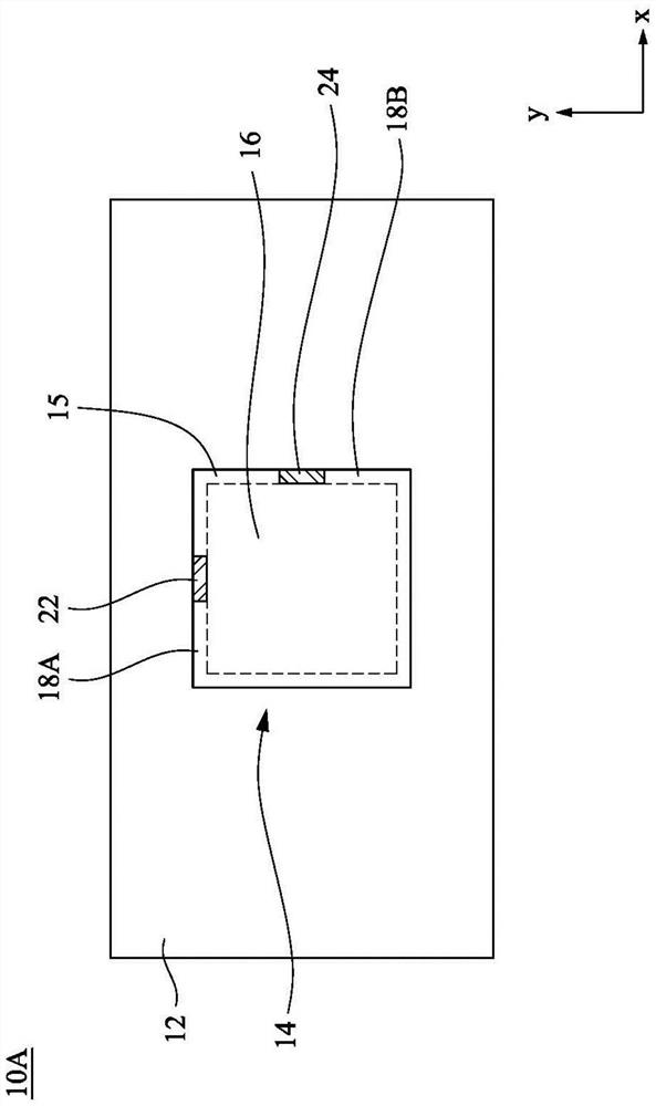
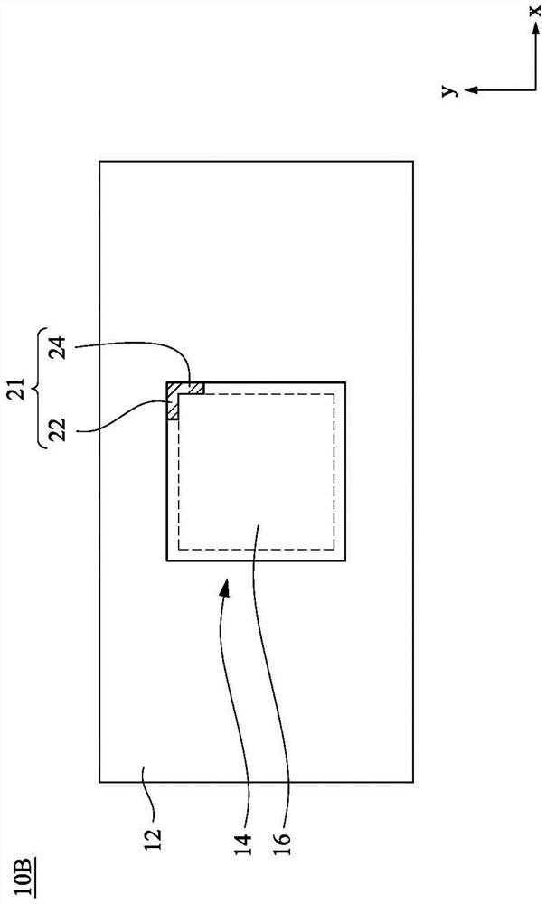
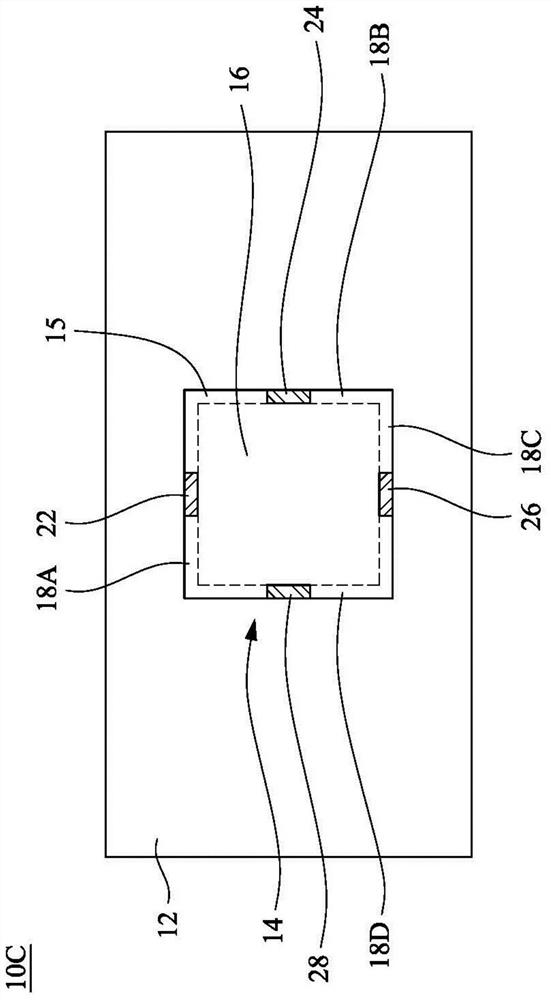
The invention discloses a circuit carrier board, which comprises: a substrate, a circuit layer structure, a metal heat dissipation block, a first fixing part, and a second fixing part. The circuit layer structure is arranged on the substrate, and the circuit layer structure includes a plurality of dielectric layers and circuits in the dielectric layers. The metal heat sink is placed in the wiring layer structure. The first fixing part is arranged on the first side of the upper surface of the metal cooling block. The second fixing part is arranged on the second side of the upper surface of the metal heat dissipation block, wherein the direction of the first side is perpendicular to the direction of the second side. A method for producing a circuit carrier is also provided here.

Description

technical field [0001] The invention relates to the technical field of printed circuit boards, in particular to a circuit carrier structure and a manufacturing method thereof. Background technique [0002] Generally speaking, in the bonding between the chip and the circuit carrier, the chip is mostly arranged on the upper surface of the circuit carrier. Since the circuit carrier does not have any positioning structure for fixing the chip, it is easy to cause deviation when placing the chip. In this case, it is very easy to cause a major impact on the accuracy of the subsequent packaging process. [0003] The offset of the chip will cause the guide hole or circuit layer formed in the subsequent process to be processed inaccurately. Therefore, reducing the offset of the chip on the circuit carrier is an urgent problem to be solved at present. Contents of the invention [0004] The main purpose of the present invention is to provide a circuit carrier and its manufacturing m...

Claims


Application Information

Patent Timeline
Patent Type & Authority Patents(China)
IPC IPC(8): H05K1/02H05K1/18H05K3/34H05K3/30
CPCH05K1/0203H05K1/185H05K3/34H05K3/301
Inventor 王梓瑄
Owner UNIMICRON TECH CORP
Why Eureka
Try Eureka