
Waste heat comprehensive energy recovery device for diesel engine

An energy recovery device and diesel engine technology, which is applied in exhaust devices, noise reduction devices, mechanical equipment, etc., can solve the problems of power generation efficiency discount, complex power transformation system, high investment, etc., to increase external output power, reduce fuel consumption rate, The effect of lowering the exhaust gas temperature

Pending Publication Date: 2021-02-23
SHANNXI DIESEL ENGINE HEAVY IND
View PDF3 Cites 6 Cited by
  • Summary
  • Abstract
  • Description
  • Claims
  • Application Information

AI Technical Summary

Problems solved by technology

[0004] However, the above four waste heat energy recovery methods each have their own disadvantages.
The first type needs to invest in waste heat boilers. Waste heat boilers are generally large in size and are used for heating, cooling and seawater desalination. Their economic efficiency is limited by factors such as seasons and fresh water demand, and they often cannot make full use of waste heat resources.
The cycle power generation efficiency of the second organic Rankine cycle system is generally less than 10%. After taking into account the power consumption of its cooling water pump and auxiliary electrical equipment, its power generation efficiency is greatly reduced; in addition, the system is complex and requires the use of high-speed motors 1. Select special power transformation equipment and system control devices, and the organic working medium is expensive, so the investment is high, the operation and maintenance costs are high, and there are still many technical bottlenecks in the sealing and control of the system that need to be broken through; third, turbocharging Although the system is simple, all the energy recovered by the former is used by the diesel engine and has been included in the working efficiency of the diesel engine, so no further comments on this equipment
If the generated electric energy needs to be connected to the grid, the power transformation system is complex and the investment is high

Method used


Image

  • Waste heat comprehensive energy recovery device for diesel engine

Examples


Embodiment approach 1

[0033] Embodiment 1: The waste heat recovery system is in normal working condition.

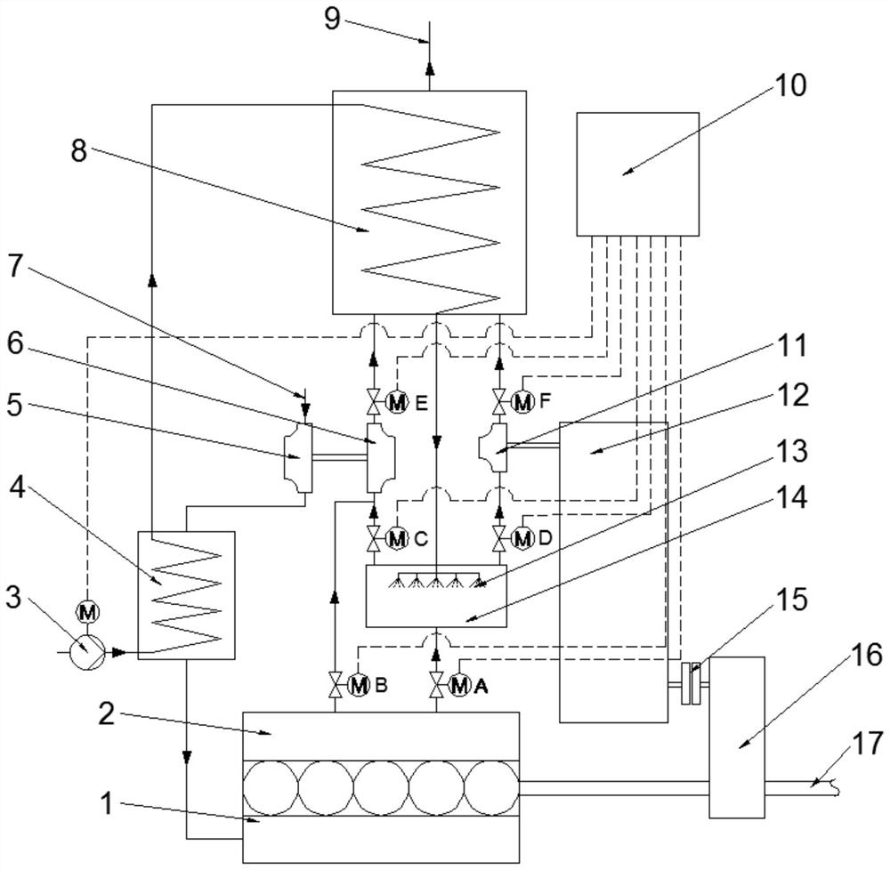
[0034] When the waste heat recovery system is working normally, control valve A, control valve C, control valve D, control valve E and control valve F are opened, control valve B is closed, and the flue gas from the main exhaust pipe 2 of the diesel engine enters the evaporator through control valve A In 14, it is mixed with the high-temperature water or steam-water mixture that comes from the water booster pump 3 and is heated by the pressurized air heat exchanger 4 and the flue gas heat exchanger 8, and enters the evaporator 14 through the nozzle 13, and in the evaporator 14 is mixed with high-temperature flue gas and quickly evaporated into superheated steam to form a mixture of superheated steam and flue gas; part of the gaseous mixture enters the exhaust gas turbocharger turbine 6 under the control of the control valve C to drive the coaxial exhaust gas turbine The supercharger compresso...

Embodiment approach 2

[0037] Embodiment 2: Diesel engine low load operating condition.

[0038] Under the condition of low load, under the control of the control device 10, the control valves A, C, and E are opened, the control valves B, D, and F are closed, the clutch 15 is disengaged, and the power turbine 11 is not engaged. Work. The high-temperature steam or steam-water mixture formed after the water flows through the water booster pump 3, the booster air heat exchanger 4 and the flue gas heat exchanger 8 is mixed, enters the evaporator 14 through the nozzle 13, and is mixed with the smoke in the evaporator 14. The gas is mixed to form a mixture of superheated steam and smoke, which only drives the exhaust turbocharger of the diesel engine to increase the pressure of the boosted air of the diesel engine, and improves the dynamic power response and working efficiency of the diesel engine under partial load conditions. The flue gas discharged from the exhaust gas turbocharger turbine 6 enters th...

Embodiment approach 3

[0040] Implementation mode 3: emergency working conditions.

[0041] When the waste heat recovery system fails to work, under the control of the control device 10, the control valve A, control valve C, control valve D, and control valve F are closed, and the control valve B and control valve E are opened. The clutch 15 is disengaged, and the system Return to the initial setting of the diesel engine, the exhaust gas in the exhaust manifold 2 of the diesel engine directly enters the exhaust turbocharger turbine 6, and drives the exhaust turbocharger to work to ensure the normal operation of the diesel engine.


PUM


Abstract

The invention provides a waste heat comprehensive energy recovery device for a diesel engine, and belongs to the technical field of energy recovery. When the waste heat comprehensive energy recovery device is used, water firstly absorbs heat through a pressurized air heat exchanger and then enters a flue gas heat exchanger to further absorb flue gas heat, generated steam or a generated steam-watermixture is atomized through a spray head, and then enters an evaporator to be mixed with high-temperature flue gas from a smoke exhaust main pipe of the diesel engine to be quickly vaporized into water vapor, on one hand, a mixture of the flue gas and the water vapor drives a waste gas turbocharger to provide supercharged air for the diesel engine, and on the other hand, the mixture drives a power turbine is driven to work; and energy recovered by the power turbine is finally fed back to an output shaft of the diesel engine through a gear transmission device, so that the energy is effectivelyutilized. The system can recycle supercharged air, lubricating oil and exhausted flue gas waste heat energy of the diesel engine to the maximum extent, the exhausted flue gas temperature of the diesel engine is effectively reduced, the proper environment temperature is provided for tail gas desulfurization of the diesel engine, the external output power of the diesel engine is increased, and thefuel consumption rate of the diesel engine is reduced.

Description

technical field [0001] The invention belongs to the technical field of energy recovery and utilization, and in particular relates to a waste heat comprehensive energy recovery device for diesel engines. Background technique [0002] The thermal efficiency of a diesel engine is generally less than 50%, and most of the remaining energy is discharged into the natural environment in the form of heat. The waste heat resources are abundant, especially for large and medium-sized diesel engines, whose stand-alone waste heat power is at the megawatt level, and the maximum stand-alone power can reach 80-100 MW. Generally, multiple large diesel engines are operated in parallel, such as land diesel engine power station system, marine diesel engine power system and power station system, offshore platform power station system, etc., as few as 2-3 units are operated in parallel, and as many as dozens of units are connected in parallel Running, the residual heat energy is very large. Ther...

Claims


Application Information

Patent Timeline
IPC IPC(8): F02G5/04F02B37/00F02B41/10F01N5/02
CPCF02G5/04F01N5/02F02B37/00F02B41/10Y02T10/12
Inventor 李策略林雪利林雪玲高会元钟兵马国燕
Owner SHANNXI DIESEL ENGINE HEAVY IND
Learn More