
Push rod type optimizing and accurate cutting-off saw

A push rod and sawing technology, which is applied in the direction of circular saws, sawing components, sawing equipment, etc., can solve the problems of low positioning accuracy, inability to press and hold, and inability to send and position wood.

Inactive Publication Date: 2021-02-12
JIANGSU JIANGJIA MACHINERY
View PDF0 Cites 2 Cited by
  • Summary
  • Abstract
  • Description
  • Claims
  • Application Information

AI Technical Summary

Problems solved by technology

However, at present, the sawing machine in the horizontal cutting equipment realizes the cutting by clamping and positioning the wood with the help of the feeding conveying roller. Although the wood conveying roller can realize the feeding and conveying of the wood, it cannot accurately send and position the wood The sawing position of the circular saw blade, and the conveying roller pair only clamps and positions the length direction of the wood, but does not perform clamping and positioning in the width direction of the wood, and the conveying roller cannot saw the wood kerf at the sawing edge of the circular saw blade. The edge is effectively pressed, not only the positioning accuracy is low, but also there are burrs on the edge of the saw end of the wood, which makes it difficult to form a high-precision wood product
At the same time, it is difficult to control the timing and position of the circular saw blade in the existing sawing machine, which also affects the sawing accuracy of the wood.

Method used


Image

  • Push rod type optimizing and accurate cutting-off saw
  • Push rod type optimizing and accurate cutting-off saw
  • Push rod type optimizing and accurate cutting-off saw

Examples


Embodiment Construction

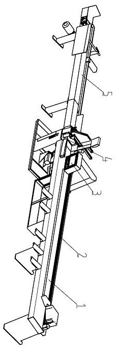
[0042] exist figure 1 The preferred push rod fine-cutting saw shown in this cross-cutting saw includes a pusher 2, a sawing machine 4 and a sawing material sorter 5, and a pusher is respectively arranged on the left and right sides of the sawing machine 4 2 and sawing material sorting machine 5. The wood to be sawed 1 is sent to the sawing machine 4 by the precise push and feeding of the pusher 2, and is cut off by horizontal sawing. ; Therefore, the pusher 2, the sawing machine 4 and the sawing material sorter 5 are arranged in sequence from front to back along the timber sawing path. The sensors and driving motors of the pusher 2, the sawing machine 4 and the sawing material sorting machine 5 are all electrically connected to the intelligent controller 3, and the intelligent controller 3 also controls the sorting cylinder of the sawing material sorting machine 5 53 Sorting actions.

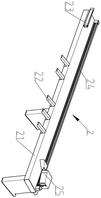
[0043] Such as figure 2 In the pusher 2 shown, a pusher electric cylinder 24 is install...


PUM


Abstract

The invention discloses a push rod type optimizing and accurate cutting-off saw. The push rod type optimizing and accurate cutting-off saw comprises a material pushing machine, a sawing machine and asawed material sorting machine which are sequentially arranged from front to back along a timber sawing path, according to the material pushing machine, the sawing machine and the sawed material sorting machine, the material pushing machine comprises a material pushing machine frame, an accurate pusher is movably arranged on the material pushing machine frame through a material pushing electric cylinder, a timber side pressing device is further arranged on the material pushing machine frame, a sawing workbench and a main motor are arranged on a sawing machine machine frame, a left clamping assembly and a right clamping assembly are arranged above the sawing workbench, a vertical pressing assembly is arranged between the left clamping assembly and the right clamping assembly, a swing cutting assembly is further installed on the sawing machine machine frame, the main motor drives a circular saw web through the swing cutting assembly, the sawed material sorting machine comprises a sortingmachine frame, a sorting conveying belt is arranged on the sorting machine frame in a stretch-draw mode, and a plurality of sorting air cylinders and sorting baffles are further arranged on the sorting machine frame. By means of the transverse cutting-off saw, sliding-free accurate pushing of timber can be achieved, and effective clamping and positioning and accurate cutting and sawing can be carried out on the wood.

Description

technical field [0001] The invention relates to the technical field of wood processing, in particular to a transverse chop saw capable of optimally and accurately chopping and sawing wood. Background technique [0002] In the wood processing industry, wood defect removal and wood grade classification are two indispensable parts. The work efficiency and accuracy of the two are directly related to the wood production efficiency. The horizontal optimal cut-off saw can actually select and determine the optimal cut-off plan through mathematical analysis and reasonable matching according to the shape, length, quality and other wood characteristics of the wood and the actual data requirements, so as to minimize the waste of wood and make the The use value of wood is fully utilized, so the horizontal optimal cut-off saw not only has a fast sawing speed and high production efficiency, but also can effectively improve the utilization rate of wood and the yield of wood. [0003] The m...

Claims


Application Information

Patent Timeline
IPC IPC(8): B27B5/06B27B5/29B27B29/02B27B31/00B27B31/08B07C5/02
CPCB27B5/06B27B5/29B27B29/02B27B31/006B27B31/08B07C5/02
Inventor 朱志林王均东臧景平
Owner JIANGSU JIANGJIA MACHINERY
Learn More