A kind of preparation method of soft-edge diaphragm resistant to laser damage
A soft-edge diaphragm and anti-laser technology, applied in laser welding equipment, welding equipment, manufacturing tools, etc., can solve problems such as the inability to economically and efficiently prepare soft-edge diaphragms with high resistance to laser damage, and achieve the threshold of laser damage. High efficiency, novel ideas, and the effect of solving thermal stress problems
- Summary
- Abstract
- Description
- Claims
- Application Information
AI Technical Summary
Problems solved by technology
Method used
Image
Examples
Embodiment 1
[0036] A method for preparing a laser-resistant soft-edge diaphragm, which is carried out according to the following steps:
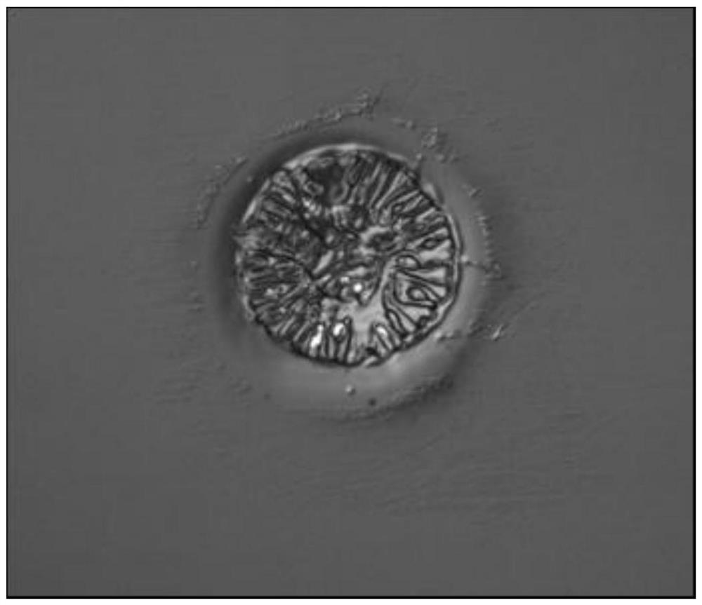
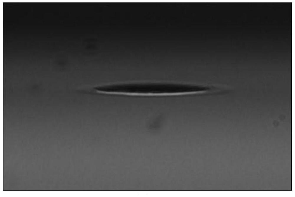
[0037] S1: Debug Focus CO 2 The power and pulse width of the laser pulses enable the focused CO 2 Laser pulse peak power 600W, pulse width 4μs, spot 1 / e 2 220 μm in diameter, irradiated on the surface of fused silica, which strongly absorbs CO 2 Rapid heating with laser energy produces phase explosion ablation, forming crack-free ablation pits. See figure 1 and figure 2 , From the micrograph of the ablation pit point, it can be observed that the irregular surface formed by the liquid splashing of the phase explosion is obvious, with a diameter of 120 μm and a depth of 5 μm.
[0038] S2: Detection of residual stress at the ablation pit point by photoelastic method.
[0039] Figure 4 and Figure 6 The dark field image of the residual stress distribution at the traditional ablation point on the surface of fused silica measured by photoelasticity me...
Embodiment 2
[0044] In this embodiment, step S1 and step S2 are the same as embodiment 1, the difference is:
[0045] S3: The density of ablation pits at the edge of the soft-edged aperture of a round hole with an aperture of 10mm gradually increases toward the direction away from the edge (that is, the closer to the edge of the soft-edged diaphragm, the greater the density of ablation pits, and the farther away from the soft-edged diaphragm the density of ablation pits increases. The edge of the edge diaphragm, the smaller the density of ablation pits), the distribution of the density of ablation pits is a 10-order super-Gaussian distribution, and the density of ablation pits in the center of the aperture of the soft edge diaphragm of the round hole changes from 50 in the center to The % duty cycle is distributed along the Gaussian diameter, and the scanning galvanometer is used to make the edge ablation pit point, and each ablation pit point is made according to the method of step S1, and...
Embodiment 3
[0049] In this embodiment, step S1 and step S2 are the same as embodiment 1, the difference is:
[0050] S3: The density of ablation pits on the edge of the soft-edged aperture of a rectangular hole with a length of 10 mm and a width of 2 mm gradually increases toward the direction away from the edge (that is, the closer to the edge of the soft-edged aperture, the greater the density of ablation pits, The farther away from the edge of the soft-edged aperture, the smaller the density of ablation pits), the edge distribution in the length direction is the 10th-order super-Gaussian distribution, and the edge distribution in the width direction is the 2nd-order super-Gaussian distribution, and the scanning galvanometer is used to make the edge burning Each ablation pit point is made according to the method of step S1, and the dark field image of the soft edge diaphragm of the rectangular hole is as follows Figure 11 shown.
[0051] S4: Use the spot quality analyzer to test the s...
PUM
| Property | Measurement | Unit |
|---|---|---|
| optical damage threshold | aaaaa | aaaaa |
| optical damage threshold | aaaaa | aaaaa |
| optical damage threshold | aaaaa | aaaaa |
Abstract
Description
Claims
Application Information
 - R&D
- Intellectual Property
- Life Sciences
- Materials
- Tech Scout
- Unparalleled Data Quality
- Higher Quality Content
- 60% Fewer Hallucinations
Browse by: Latest US Patents, China's latest patents, Technical Efficacy Thesaurus, Application Domain, Technology Topic, Popular Technical Reports.
© 2025 PatSnap. All rights reserved.Legal|Privacy policy|Modern Slavery Act Transparency Statement|Sitemap|About US| Contact US: help@patsnap.com


