Combustor with adjustable combustion atmosphere and experimental method
A burner and atmosphere technology, applied in combustion methods, combustion chambers, combustion equipment, etc., can solve the problems of not wide application of fuel, single atmosphere, etc., and achieve the effects of convenient operation, convenient operation and simple structure design.
- Summary
- Abstract
- Description
- Claims
- Application Information
AI Technical Summary
Problems solved by technology
Method used
Image
Examples
specific Embodiment 1
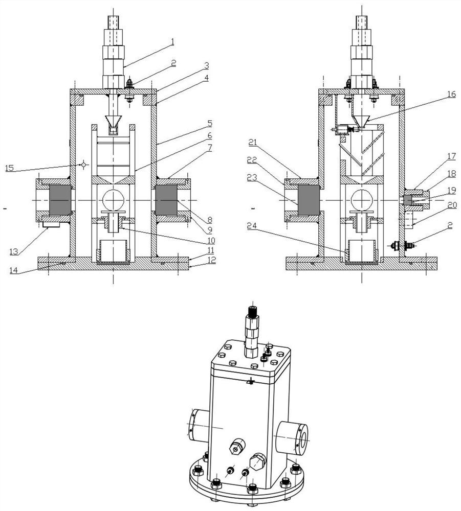
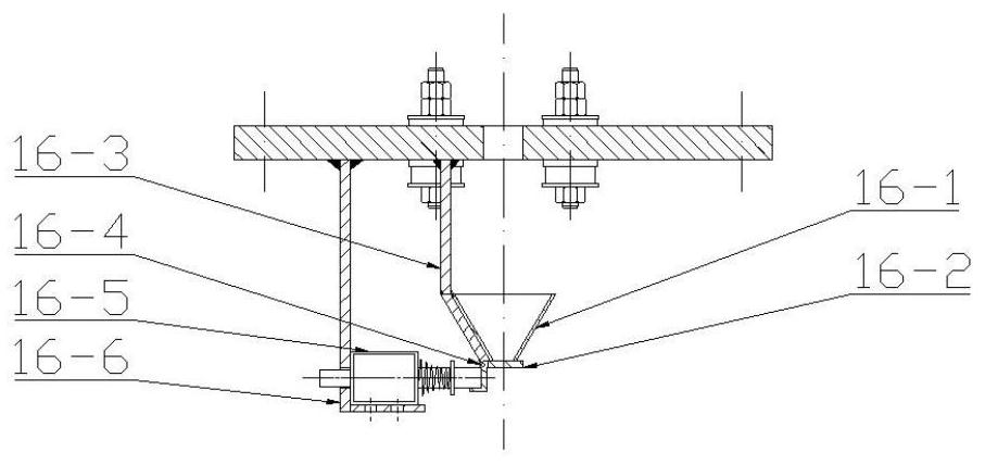
[0056]Step 1. Install the O-ring 14 between the main body of the combustion chamber and the bottom plate 12 of the combustion chamber and fasten it with bolts. Fill the corresponding O-rings in the laser incident window 17, the quartz glass observation window 7 and the laser stopper window 21 respectively. Press the quartz glass 8, the germanium glass 19, and the laser block 23 into the corresponding windows respectively, and screw into the corresponding pressing screws, and tighten them with a hook wrench. The sealing electrode 2 is respectively loaded into the burner side wall 5 and the burner top plate 3, and the electromagnet 16-5 of the powder fuel sampling mechanism 3 is connected to the sealing electrode 2 of the burner top plate 3, and the top surface of the burner top plate The female thread of the check valve is externally connected to the male thread, and tightened with a wrench.
[0057] Screw the four-way interface into the burner air inlet / outlet 15, and the othe...
specific Embodiment 2
[0060] Step 1. Install the O-ring 14 between the main body of the combustion chamber and the bottom plate 12 of the combustion chamber and fasten it with bolts. Fill the corresponding O-rings in the laser incident window 17, the quartz glass observation window 7 and the laser stopper window 21 respectively. Press the quartz glass 8, the germanium glass 19, and the laser block 23 into the corresponding windows respectively, and screw into the corresponding pressing screws, and tighten them with a hook wrench. The sealing electrode 2 is respectively loaded into the burner side wall 5 and the burner top plate 3, and the electromagnet 16-5 of the powder fuel sampling mechanism 3 is connected to the sealing electrode 2 of the burner top plate 3, and the top surface of the burner top plate The female thread of the check valve is externally connected to the male thread, and tightened with a wrench.
[0061] Screw the four-way interface into the burner air inlet / outlet 15, and the oth...
specific Embodiment 3
[0067] Step 1. Install the O-ring 14 between the main body of the combustion chamber and the bottom plate 12 of the combustion chamber and fasten it with bolts. Fill the corresponding O-rings in the laser incident window 17, the quartz glass observation window 7 and the laser stopper window 21 respectively. Press the quartz glass 8, the germanium glass 19, and the laser block 23 into the corresponding windows respectively, and screw into the corresponding pressing screws, and tighten them with a hook wrench. The sealing electrode 2 is respectively loaded into the burner side wall 5 and the burner top plate 3, and the electromagnet 16-5 of the powder fuel sampling mechanism 3 is connected to the sealing electrode 2 of the burner top plate 3, and the top surface of the burner top plate The female thread of the check valve is externally connected to the male thread, and tightened with a wrench.
[0068] Screw the four-way interface into the burner air inlet / outlet 15, and the oth...
PUM
 Abstract
Description
Claims
Application Information
 - R&D
- Intellectual Property
- Life Sciences
- Materials
- Tech Scout
- Unparalleled Data Quality
- Higher Quality Content
- 60% Fewer Hallucinations
Browse by: Latest US Patents, China's latest patents, Technical Efficacy Thesaurus, Application Domain, Technology Topic, Popular Technical Reports.
© 2025 PatSnap. All rights reserved.Legal|Privacy policy|Modern Slavery Act Transparency Statement|Sitemap|About US| Contact US: help@patsnap.com


