
Sintering device for sintering neodymium-iron-boron magnet, and using method thereof

A sintering device, NdFeB technology, applied in the manufacture of magnetic objects, magnetic materials, inductors/transformers/magnets, etc., can solve the problem of not gradually cooling the furnace, and achieve the effect of slowing down the flow rate

Active Publication Date: 2021-02-05
JIANGXI UNIV OF SCI & TECH +1
View PDF5 Cites 3 Cited by
  • Summary
  • Abstract
  • Description
  • Claims
  • Application Information

AI Technical Summary

Problems solved by technology

[0006] The technical problem to be solved by the present invention is to provide a sintering device for sintering NdFeB magnets and its use method, one of which is to have a heat dissipation function and solve the problem that the temperature inside the furnace cannot be gradually lowered after sintering is completed; the other The first purpose is to solve the problem of the degree of heating of the magnet in the furnace, so as to achieve the effect of increasing the sintering quality of the magnet without using a stirring device, and the other purpose is to have mechanical feeding, which is convenient for placing and taking out the magnet , to avoid direct contact between the staff and the heating element, which solves the problem of taking

Method used


Image

  • Sintering device for sintering neodymium-iron-boron magnet, and using method thereof
  • Sintering device for sintering neodymium-iron-boron magnet, and using method thereof
  • Sintering device for sintering neodymium-iron-boron magnet, and using method thereof

Examples


Embodiment 1

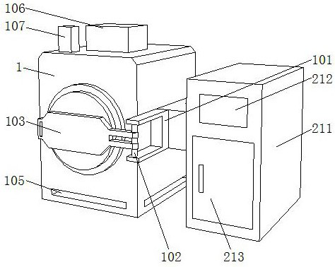
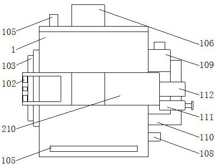
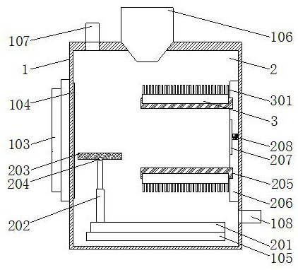
[0034] Such as Figure 1-Figure 8 As shown, the present invention provides a sintering device for sintering NdFeB magnets and a method for using the same, a furnace body 1 , a furnace chamber 2 and a water-cooled elbow 3 .

[0035] In this embodiment, the body of furnace 1 includes a hearth 2, a connection plate 206 is fixedly installed on one side of the interior of the hearth 2, a groove is provided on the front of the connection plate 206, and a lifting rod 209 is arranged inside the groove, and the lifting rod 209 Heating elements 205 are slidingly connected to the outer wall of the outer wall, and the number of heating elements 205 is two. One side surface of each heating element 205 is fixedly installed with a water-cooled elbow 3. Through exquisite design, the combination of water-cooled elbow 3 and heating element 205 Combined, it is convenient to carry out the first step of heat dissipation for the heating element 205 and the magnet above it, avoiding the problem of d...

Embodiment 2

[0039] Such as figure 1 As shown, on the basis of Embodiment 1, the present invention provides a technical solution: a fixed block 101 is fixedly installed on the right side surface of the furnace body 1, and a connecting rod 102 is fixedly connected to the inside of the fixed block 101, and the fixed block 101 is fixed by setting The connecting rod 102 of the connecting rod 102 is rotatably connected with a furnace cover 103, and the inside of the furnace cover 103 is provided with a sealing strip 104 to ensure the sealing of the inside of the furnace 2. The bottom of the furnace body 1 is provided with a cavity 105 to prevent the bottom of the furnace body 1 from being directly connected to the ground. Contact, the lower ground temperature affects the temperature at the bottom of the body of furnace 1, so that the bottom of the body of furnace can normally dissipate heat and keep warm. The back side of the fixed block 101 is fixedly connected with a control block 210, and the...

Embodiment 3

[0041] Such as Figure 1-2 As shown, on the basis of Embodiment 1 and Embodiment 2, the present invention provides a technical solution: preferably, a vacuum pump 106 is fixedly installed on the top of the furnace body 1, and an air inlet 107 is arranged on the left side of the vacuum pump 106, and the furnace The back of the furnace body 1 is fixedly connected with a circulating water pipe 110, and the back of the furnace body 1 is fixedly connected with an air outlet 108. An air valve is arranged inside the air inlet 107 and the air outlet 108. After local heat dissipation, the air inlet is controlled by the air valve. 107 and the gas flow of the gas outlet 108, further gradually cooling the inside of the furnace 2, a negative pressure water pump 111 is fixedly installed on the outer wall of the circulating water pipe 110, a condenser 112 is arranged above the negative pressure water pump 111, and the top side of the circulating water pipe 110 A water inlet tank 109 is fixed...


PUM


Abstract

The invention discloses a sintering device for sintering a neodymium-iron-boron magnet, and a using method thereof, and relates to the technical field of neodymium-iron-boron magnet production. The sintering device comprises a furnace body, a hearth and water cooling bent pipes, the furnace body comprises the hearth, a connecting plate is fixedly installed on one side in the hearth, a groove is formed in the front face of the connecting plate, and a lifting rod is arranged in the groove; and two heating elements are slidably connected to the outer wall of the lifting rod, and one water coolingbent pipe is fixedly mounted on the surface of one side of each heating element. By adopting the combined arrangement of a rotating piece and a flow guide piece in each water cooling bent pipe, the unequal flow guide pieces are arranged at the two ends of each rotating piece, one end of each rotating piece has power, certain force is generated under the driving of water flow to guide the water flow to the flow guide pieces, and due to the fact that a pipeline is filled with water when the flow guide pieces are turned, the water flow direction is disordered, so the flowing speed of water is reduced, the duration of cold water contacting with the heating elements is prolonged, water flows spirally in the pipeline, and the water continuously performs heat absorption and heat dissipation movement.

Description

technical field [0001] The invention relates to a sintering device, relates to the technical field of NdFeB magnet production, in particular to a sintering device for sintering NdFeB magnets and a use method thereof. Background technique [0002] The orbital servo motor is mainly composed of a stator and a rotor. The rotor is generally made of permanent magnets, and it uses neodymium magnets. Neodymium magnets are also called neodymium iron boron magnets, which are tetragonal crystal systems formed by neodymium, iron, and boron. Crystal, the magnetic energy product of this kind of magnet is greater than that of samarium cobalt magnet. The magnet is the permanent magnet second only to the absolute zero holmium magnet, and it is also the most commonly used rare earth magnet. NdFeB magnets are widely used in electronic products, such as hard drives, mobile phones, earphones, and battery-powered tools. [0003] Sintering is a necessary step in the production of NdFeB magnets, a...

Claims


Application Information

Patent Timeline
IPC IPC(8): H01F41/02H01F1/057
CPCH01F41/0253H01F1/0577
Inventor 喻玺杨斌杨牧南汪航李家节庞再升刘滨袁惟仁
Owner JIANGXI UNIV OF SCI & TECH
Learn More