
Two-stage superheater desuperheating water system capable of independently taking water

A secondary superheater and superheater technology, applied in the control of superheated temperature, steam superheating, lighting and heating equipment, etc., can solve the problem of increasing the operating workload of operators, small pressure difference between desuperheating water and superheated steam, and superheating desuperheating water. Problems such as the inability to put into operation normally, to achieve the effect of not affecting the cooling effect, improving the steam temperature, and not increasing the operation switching operation

Pending Publication Date: 2021-02-02
XIAN THERMAL POWER RES INST CO LTD +1
View PDF9 Cites 1 Cited by
  • Summary
  • Abstract
  • Description
  • Claims
  • Application Information

AI Technical Summary

Problems solved by technology

In recent years, with the increasing pressure of thermal power units to save energy and reduce emissions, some power plants (mainly power plants equipped with 600MW subcritical units and below) have implemented energy-saving renovations for the outlets of superheated desuperheating water systems, and new overheating has occurred after the renovation. The situation that the desuperheating water cannot be put into normal operation is specifically reflected in the following three aspects: first, the actual desuperheating water volume of the superheater in most load sections after transformation exceeds the design margin so that the desuperheating effect cannot be achieved; second, the desuperheating water after transformation and The pressure difference between the superheated steam is too small so that the spray cooling effect is poor; third, there is a switch between new and old water sources in the high-load section after the transformation, which significantly increases the workload of operators

Method used


Image

  • Two-stage superheater desuperheating water system capable of independently taking water

Examples


Embodiment Construction

[0017] The present invention is described in further detail below in conjunction with accompanying drawing:

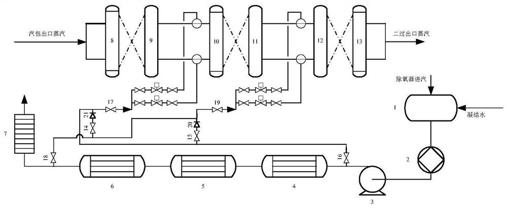
[0018] refer to figure 1 , the two-stage superheater desuperheating water system for independently taking water according to the present invention includes a deaerator 1, a front pump 2, a feed water pump 3, a No. 3 high-pressure heater 4, a first main pipe electric gate valve 16, and a No. 2 high-pressure heating Device 5, No. 1 high-pressure heater 6, economizer 7, second main pipe electric gate valve 18, first electric contact gate valve 15, first contact main pipe check valve 20, main pipe of secondary water supply system under separate water intake mode Electric gate valve 19, separate water intake mode, the main pipe electric gate valve of the next stage water supply system 17, the second electric contact gate valve 14, the second contact main pipe check valve 21, the inlet header of the panel superheater 10, the inlet header of the second stage superheater Box ...


PUM


Abstract

The invention discloses a two-stage superheater desuperheating water system capable of independently taking water. The two-stage superheater desuperheating water system comprises a deaerator, a waterfeeding pump, a third high-pressure heater, a first main pipe electric gate valve, a second high-pressure heater, a first high-pressure heater, an economizer, a second main pipe electric gate valve, afirst electric contact gate valve, a first contact main pipe check valve, a second-stage water supply system main pipe electric gate valve in an independent water taking mode, a first-stage water supply system main pipe electric gate valve in an independent water taking mode, a second electric contact gate valve, a second contact main pipe check valve, a platen superheater inlet header, a second-stage superheater inlet header, a steam pocket outlet steam pipeline, a first-stage superheater inlet header, a first-stage superheater outlet header, a platen superheater outlet header, a second-stage superheater outlet header and a steam output pipeline. The system can guarantee the cooling effect of superheated steam water spraying, the spray cooling effect is good, and the operation workload of operators is small.

Description

technical field [0001] The invention belongs to the field of superheater desuperheater water for power plant boilers, and relates to a two-stage superheater desuperheater water system for taking water separately. Background technique [0002] The superheater desuperheater water of power plant boiler usually adopts two-stage desuperheater setting, which is divided into the first-stage desuperheater of the superheater and the second-stage desuperheater of the superheater. The primary desuperheater of the superheater is located on the outlet of the primary pass and the inlet conduit of the screen pass, and is arranged symmetrically on the left and right. The secondary desuperheater of the superheater is located on the outlet of the screen and the inlet of the second pass, and is arranged symmetrically on the left and right. The body of the superheater desuperheater includes a cylinder, a nozzle, a Venturi mixing tube and a bushing, etc. In the temperature control of superheat...

Claims


Application Information

Patent Timeline
Patent Type & Authority Applications(China)
IPC IPC(8): F22G5/12F22G3/00
CPCF22G5/12F22G3/00
Inventor 王勇李杨林琳井新经周刚周元祥王宏武张奔李耀锋宋佳佳
Owner XIAN THERMAL POWER RES INST CO LTD
Learn More