Water spraying device for milling based on precision numerical control machine tool
A technology of milling processing and water spraying device, which is applied in the direction of metal processing equipment, metal processing machinery parts, milling machine equipment, etc., can solve the problems of no liquid recovery device, affecting production efficiency, cumbersome operation, etc., to improve the convenience of connection, The effect of improving production efficiency and improving flushing effect
- Summary
- Abstract
- Description
- Claims
- Application Information
AI Technical Summary
Problems solved by technology
Method used
Image
Examples
Embodiment 1
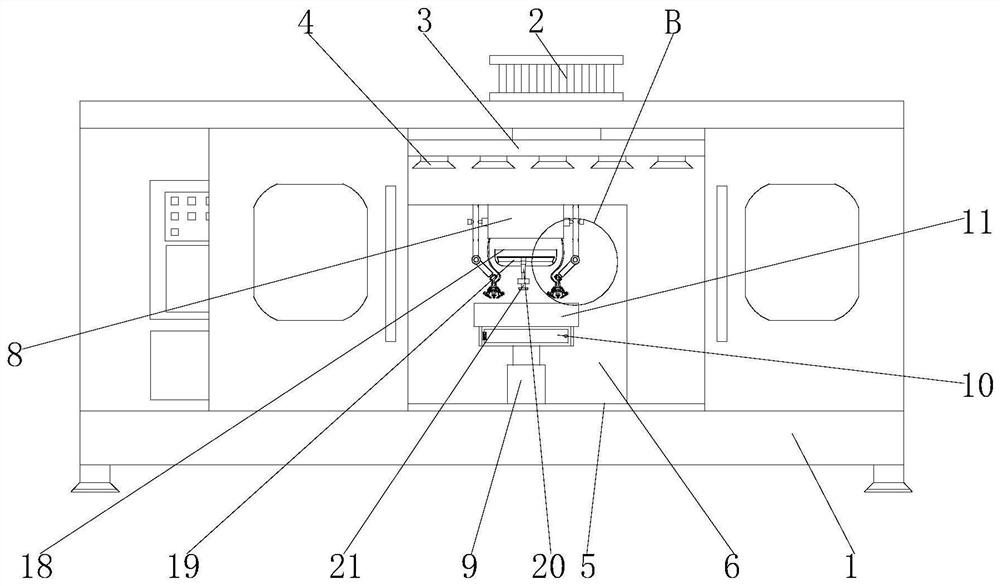
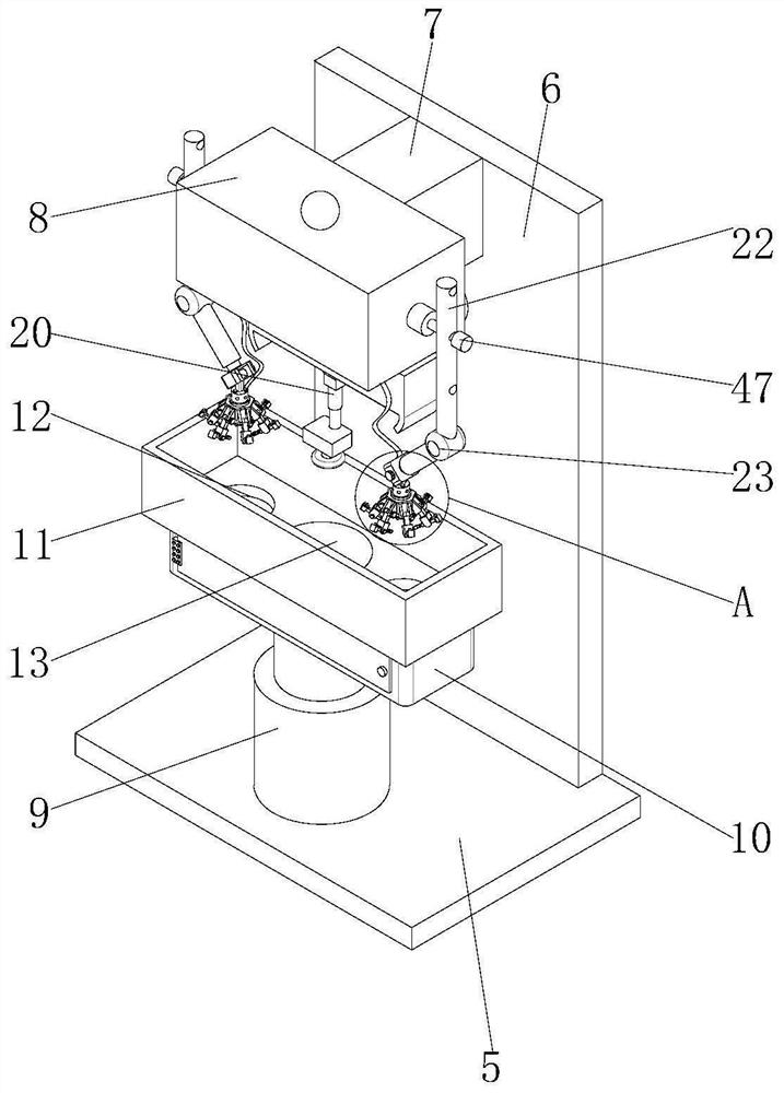
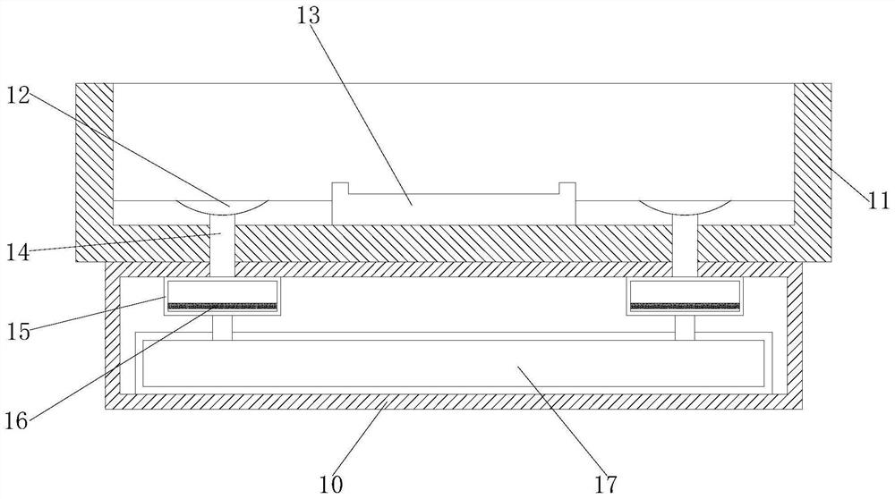
[0029] see Figure 1-7 , the present invention provides a technical solution: a water spray device based on precision CNC machine tool milling, including a machine tool shell 1, a dust collector 2 is fixedly installed on the top of the machine tool shell 1, and a fixed pipe is fixedly installed inside the machine tool shell 1 3. The bottom of the fixed pipe fitting 3 is fixedly installed with an air expansion cover 4, the inside of the machine tool shell 1 is fixedly installed with a base base 5, the top of the base base 5 is fixedly installed with a fixed plate 6, and the top of the base base 5 is fixedly installed with a telescopic column body 9, the top of the telescopic cylinder 9 is fixedly equipped with a water collecting tank 10, the top of the water collecting tank 10 is fixedly installed with a working frame 11, the inside of the working frame 11 is fixedly installed with a limit piece 13, and the inside of the working frame 11 is provided with a water collecting hole ...
Embodiment 2
[0032] see Figure 1-7 , on the basis of Embodiment 1, the present invention provides a technical solution: a fixed block 18 is fixedly installed on the front of the fixed plate 6, a groove is opened inside the fixed block 18, and a fixed rod is fixedly installed inside the groove 19, the outside of the fixed rod 19 is fixed with a sliding sleeve, and the bottom of the sliding sleeve is fixed with a first telescopic rod 20, and the bottom of the first telescopic rod 20 is fixed with a blade 21, and the connecting pipe 14 runs through the working frame 11 extends to the inside of filter box 15, and the positive switch cabinet door of water collection box 10 is movably installed, and the specification size of filter screen 16 is compatible with the specification size of filter box 15.
[0033] In this embodiment, a fixed block 18 is fixedly installed on the front of the fixed plate 6 and a groove is provided inside it, so that the installation of the fixed rod 19 is more conveni...
Embodiment 3
[0035] see Figure 1-7 , on the basis of Embodiment 1 and Embodiment 2, the present invention provides a technical solution: the front of the fixed plate 6 is fixedly installed with a connecting plate 7, and the end of the connecting plate 7 is fixedly installed with a water storage tank 8, the storage Both ends of the water tank 8 are fixedly equipped with connectors 22, one side of the connector 22 is fixedly equipped with a locking block 47, the end of the connector 22 is fixedly installed with a first rotating shaft 23, and the end of the first rotating shaft 23 is fixed. A fixing part is installed, and a second rotating shaft 46 is movably installed on the end of the fixing part.
[0036] In this embodiment, the connecting plate 7 is fixedly installed on the front of the fixed plate 6, which is convenient for the installation operation related to the water storage tank 8, and the connecting parts 22 are fixedly installed on both ends of the water storage tank 8, so that d...
PUM
 Abstract
Description
Claims
Application Information
 - R&D
- Intellectual Property
- Life Sciences
- Materials
- Tech Scout
- Unparalleled Data Quality
- Higher Quality Content
- 60% Fewer Hallucinations
Browse by: Latest US Patents, China's latest patents, Technical Efficacy Thesaurus, Application Domain, Technology Topic, Popular Technical Reports.
© 2025 PatSnap. All rights reserved.Legal|Privacy policy|Modern Slavery Act Transparency Statement|Sitemap|About US| Contact US: help@patsnap.com


