Synchronous lifting device of corrugated pipe connector and load driving device

A technology of synchronous lifting and coupling, applied in the direction of lifting device, lifting frame, etc., can solve the problems such as the inability to ensure that the attitude of the load rotating body remains unchanged, the workload is large, and the labor is wasted, so as to achieve a simple structure, liberate labor, and improve work efficiency. Effect

Active Publication Date: 2021-01-26
SHANGHAI SPACEFLIGHT INST OF TT&C & TELECOMM
View PDF11 Cites 2 Cited by
  • Summary
  • Abstract
  • Description
  • Claims
  • Application Information

AI Technical Summary

Problems solved by technology

[0004] Since the current test method is: multiple testers simultaneously rotate the screws between the load base and the load rotating body around the load rotating body, so that the load rotating body moves up and down in translation, and the strength of each tester's rotation and the speed cannot be exactly the same, so it is impossible to ensure that the posture of the load rotating body remains unchanged during the lifting process. This method requires a lot of work and wastes labor.

Method used


Image

  • Synchronous lifting device of corrugated pipe connector and load driving device
  • Synchronous lifting device of corrugated pipe connector and load driving device
  • Synchronous lifting device of corrugated pipe connector and load driving device

Examples


Embodiment 1

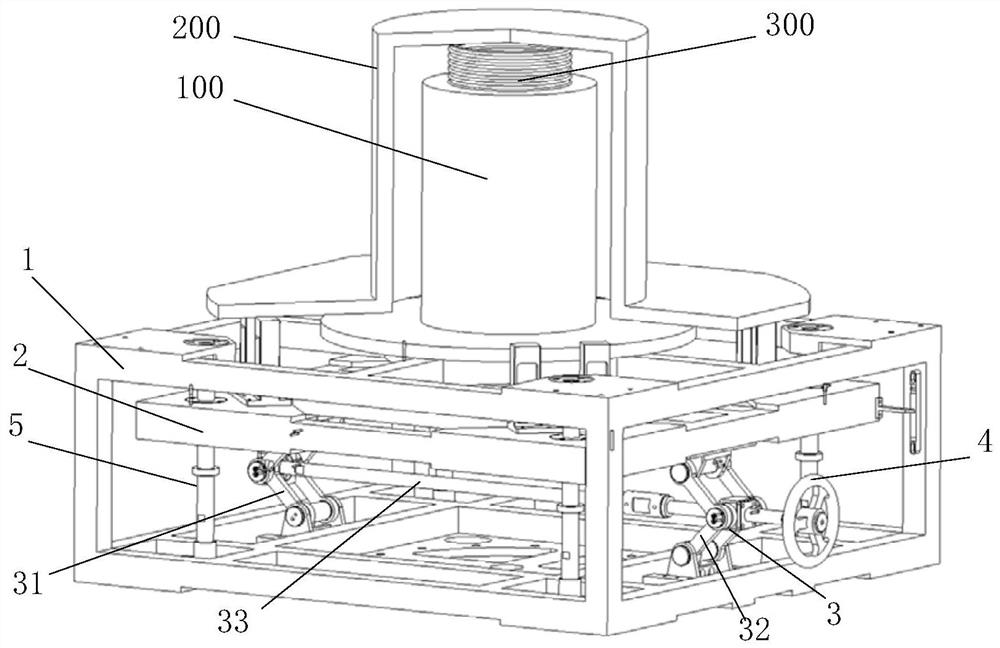
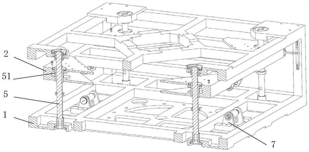
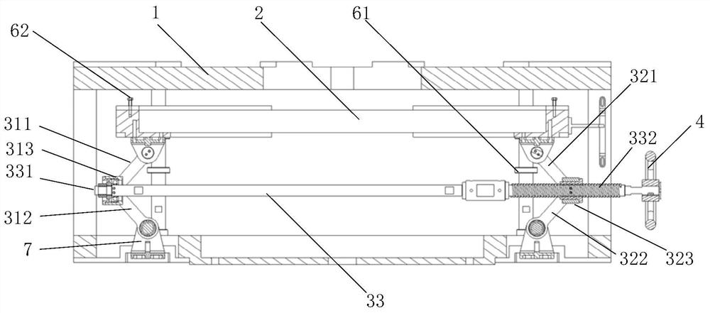
[0044] This embodiment provides a synchronous lifting device for bellows couplings, see Figure 1-Figure 7 , is a structural schematic diagram of the lifting device of this embodiment, the lifting device includes a frame 1, a load carrying mechanism 2, a connecting rod driving mechanism 3 and an operating mechanism 4: the frame 1 is used to install the load base 100, the frame 1 is a square frame, and the load base 100 is fixedly installed on the top frame structure of the frame 1. The load carrying mechanism 2 is a lifting plate for installing the load rotating body 200. The load carrying mechanism 2 is arranged in the frame 1 and can freely rise and fall; the link driving mechanism 3 is arranged on the frame 1 and the load carrying mechanism 2. Between, one end of the connecting rod driving mechanism 3 is hinged on the bottom frame of the frame 1, and the other end of the connecting rod driving mechanism 3 is hinged below the load carrying mechanism 2; the operating mechanis...


PUM


Abstract

The invention discloses a synchronous lifting device of a corrugated pipe connector. The synchronous lifting device comprises a rack, a load bearing mechanism, a connecting rod lifting mechanism and acontrol mechanism, wherein the load bearing mechanism is arranged in the rack; the connecting rod lifting mechanism is arranged between the rack and the load bearing mechanism, one end of the connecting rod lifting mechanism is fixed to the rack, and the other end of the connecting rod lifting mechanism is fixed below the load bearing mechanism; and the control mechanism is connected with the connecting rod lifting mechanism and used for driving the connecting rod lifting mechanism to ascend and descend, and therefore the load bearing mechanism is driven to ascend and descend. The invention further discloses a load driving device. According to the synchronous lifting device of the corrugated pipe connector, synchronous lifting of the periphery of a corrugated pipe can be achieved only byoperating the control mechanism by one tester, and lifting motion of a load rotating body is guaranteed; the posture is not changed in the lifting process, a falling plug is protected, the working efficiency can be improved, and the safety of equipment and personnel is guaranteed; and the synchronous lifting device has the beneficial effects of being simple in structure and easy to achieve, the labor force is liberated, and the working efficiency is improved.

Description

technical field [0001] The invention relates to an elevating device, in particular to a synchronous elevating device used for ground testing experiments of a load rotating body and a load base. Background technique [0002] Many satellite payloads have an on-orbit mechanical scanning function. In order to protect the mechanical scanning drive mechanism, ensure the reliability and on-orbit life of the scanning drive mechanism, the scanning drive mechanism is often not subjected to force during the launch phase, and the scanning drive mechanism is installed on the load base. Inside the seat, bellows couplings are often used to connect the load rotating body and the scanning drive mechanism. The load base and the load rotating body are fixed separately during the launch phase, thus avoiding the mutual influence of the vibration response of the load rotating body and the load base, and protecting the scanning drive mechanism inside the load base as well as the load rotating body...

Claims


Application Information

Patent Timeline
Patent Type & Authority Applications(China)
IPC IPC(8): B66F7/06B66F7/28
CPCB66F7/0633B66F7/0608B66F7/28
Inventor 刘建坤翁艺航南江红叶志彪赵志杰邢瑞先王光辉
Owner SHANGHAI SPACEFLIGHT INST OF TT&C & TELECOMM
Why Eureka
Try Eureka