


Quick Research
Generate reliable direction feasibility study reports for your R&D in just a few steps.

Technical Q&A
Discover and master advanced knowledge NOW. Basics, ideas, possibilities, all at once.

Find Solutions
As an expert in R&D theories, this can generate solutions to your technical problems instantly.

Evaluate Feasibility
Analyze your overall solution with one click, know your potential R&D risks in advance.

Monitor Landscape
Get weekly tech updates, stay abreast of the latest tech innovations and key insights.
A cooling connection device at the joint of a large-capacity optical fiber cable
An optical fiber cable and connecting device technology, which is applied to the field of cooling and connecting devices at large-capacity optical fiber cable joints, can solve the problems of difficulty in ensuring that the interface is uniformly fixed, high heat generation at the joint, and difficulty in ensuring accurate manual alignment of optical fiber connections. The effect of reducing the possibility of water ingress and full contact convenience
- Summary
- Abstract
- Description
- Claims
- Application Information
AI Technical Summary
Problems solved by technology
Method used
Image

Examples
Embodiment 1
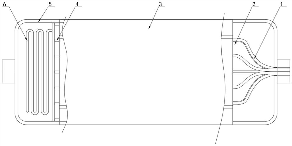
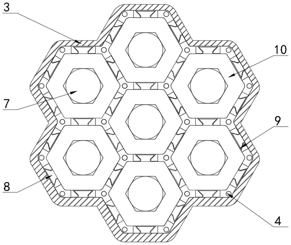
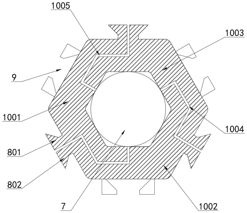
[0034] see Figure 1-5 The present invention provides a technical solution: a cooling connection device at a large-capacity optical fiber cable joint, comprising a plurality of optical fiber lines 1 and a center shell 3 arranged outside the optical fiber lines 1, and side shells are connected on both sides of the center shell 3 body 5, the inner surface wall of the side shell 5 is clamped with a heat dissipation pipe 6, and the heat dissipation pipe 6 is connected with a cooling liquid pipe 4; The inner cavity is clamped with a plurality of unit casings 10, and three clamping pieces 8 and three clamping grooves 9 are respectively opened on the outer wall of the unit casing 10 in six directions, and an extrusion cavity is opened at the central axis of the unit casing 10. 7, and the parts of the inner cavity of the extrusion cavity 7 close to the end faces of both ends are provided with threaded grooves 705, and the extrusion cavity 7 is screwed and connected with the stabilizin...
Embodiment 2
[0036] see Figure 2-Figure 5, the central shell 3 has a honeycomb-shaped structure, the side of the arc-shaped bracket 2 away from the central shell 3 has an onion-shaped structure, and the optical fiber line 1 is attached and fixed to the outer wall of the arc-shaped bracket 2, so that the arc-shaped bracket 2 can be used for the optical fiber line. The bending of 1 forms a limit to prevent the optical fiber line 1 from being bent and damaged by force. The clamping pieces 8 and the clamping grooves 9 on the unit housing 10 are arranged at intervals from each other. The card slot 9 is connected with the unit housing 10, so as to facilitate the fixation between multiple unit housings 10 and the fixation between the central housing 3 and the unit housing 10. The unit housing 10 is provided with a first sub-shell inside. The body 1001, the second sub-shell 1002 and the third sub-shell 1003 have three parts. The first sub-shell 1001, the second sub-shell 1002 and the third sub-sh...
PUM
 Abstract
Description
Claims
Application Information
 - R&D Engineer
- R&D Manager
- IP Professional
- Industry Leading Data Capabilities
- Powerful AI technology
- Patent DNA Extraction
Browse by: Latest US Patents, China's latest patents, Technical Efficacy Thesaurus, Application Domain, Technology Topic, Popular Technical Reports.
© 2024 PatSnap. All rights reserved.Legal|Privacy policy|Modern Slavery Act Transparency Statement|Sitemap|About US| Contact US: help@patsnap.com