
Power assembly rear suspension and clutch booster integrated support and rear suspension device

A technology of powertrain and booster, applied in the direction of power unit, control unit, jet propulsion unit, etc., can solve the problems of poor stability and large number of parts, and achieve the effect of improving stability and reducing the number of parts.

Pending Publication Date: 2021-01-12
DONGFENG SHENYU VEHICLE CO LTD
View PDF0 Cites 0 Cited by
  • Summary
  • Abstract
  • Description
  • Claims
  • Application Information

AI Technical Summary

Problems solved by technology

[0004] The embodiment of the present application provides a powertrain rear suspension and clutch booster integrated bracket and rear suspension device to solve the problems of poor stability and large number of parts in the suspension device in the related art

Method used


Image

  • Power assembly rear suspension and clutch booster integrated support and rear suspension device
  • Power assembly rear suspension and clutch booster integrated support and rear suspension device
  • Power assembly rear suspension and clutch booster integrated support and rear suspension device

Examples


Embodiment 1

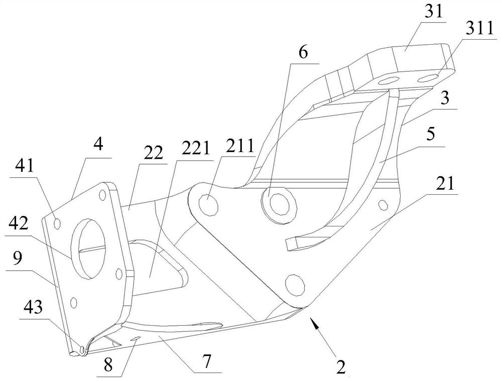
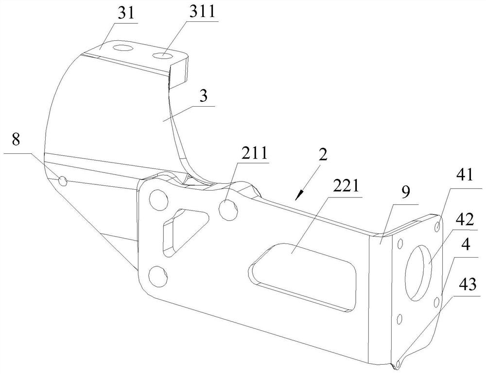
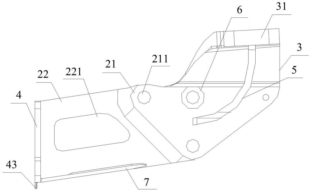
[0030] see Figure 1 to Figure 3 As shown, the embodiment of the present application provides a powertrain rear suspension and clutch booster integrated bracket, which includes a base 2, a variable-section connecting plate 3 and a fixing plate 4, and the base 2 includes a closely connected mounting plate 21 and an extension plate 22. The thickness of the extension plate 22 is lower than that of the mounting plate 21, and it is used to place the clutch booster 10. The mounting plate 21 is provided with a plurality of first mounting holes 211, and the number of the first mounting holes 211 is preferably three. The base 2 Installed on the side of the gearbox 1 through three first mounting holes 211 with a diameter of 18 mm, the height of the base 2 can be set to 105 mm, the width to 110 mm, and the thickness to 28 mm, and the three third bottom parts of the base 2 can be set to A part of the center of a mounting hole 211 is dug out to further reduce the weight of the bracket to a...

Embodiment 2

[0036] On the basis of embodiment 1:

[0037] see figure 1 As shown, the integrated bracket also includes a reinforced connecting plate 7, the reinforced connecting plate 7 is set to be arc-shaped and its rounded edge is also set to be arc-shaped, one side is connected with the extension plate 22, and the other side is connected with the fixed plate 4, That is, the extension plate 22 of the base 2 is fixedly connected to the fixed plate 4 through the reinforced connecting plate 7, which can disperse the stress between the extended plate 22 and the fixed plate 4, avoid stress concentration, and further strengthen the stability of the integrated bracket ; see figure 1 with figure 2 As shown, the reinforcing connecting plate 7 and the mounting plate 21 are provided with pipe clip fixing holes 8, and the pipe clip fixing holes 8 are used for fixing pipelines, so as to facilitate the wiring and arrangement of pipelines.

Embodiment 3

[0039] On the basis of embodiment 1:

[0040] see figure 2 As shown, the extension plate 22 of the base 2 is provided with a hollow structure 221, which is to hollow out part of the structure in the extension plate 22, so that there is no redundant material in the integrated bracket, and the hollow structure 221 can further play a role in weight reduction. function, and then realize the lightweight purpose of the integrated bracket.


PUM


Abstract

The invention relates to the technical field of peripheral parts of automobile power assemblies, in particular to a power assembly rear suspension and clutch booster integrated support and a rear suspension device. The support comprises a base, a variable cross-section connecting plate and a fixing plate. Since the base is installed on the side of a gearbox, a soft pad mounting surface of the variable cross-section connecting plate is used to install a vibration isolation soft pad, the fixing plate is used for installing a clutch booster, namely, suspension fixation and clutch booster installation are integrated and then fixed to the side face of the gearbox through the base to form four-point suspension, sliding friction between the rear suspension support and the clutch booster support is avoided, fatigue abrasion is reduced, and the risk that the rear suspension device is broken is reduced. Moreover, the soft pad mounting surface is located above the side of a first mounting hole, so that sufficient space is reserved for the mounting of the clutch booster, and the soft pad mounting surface is far away from the mass center of a power assembly, and therefore, the stability of therear suspension device can be effectively improved, and the number of parts can be effectively reduced.

Description

technical field [0001] The present application relates to the technical field of peripheral components of automobile powertrain, in particular to a powertrain rear suspension and clutch booster integrated bracket and rear suspension device. Background technique [0002] Automobile powertrain refers to a series of parts and components that generate power on the vehicle and transmit the power to the road surface. It is generally supported on the frame by a suspension device; the suspension device is used to support the power unit (engine and transmission) Weight, suppress the dynamic displacement of the power plant caused by the external force of the internal reaction force and prevent the vibration force from the engine, etc. from being transmitted to the body. [0003] In the prior art, the automobile powertrain is generally supported on the vehicle frame by a six-point suspension structure (engine front suspension, flywheel housing suspension and gearbox auxiliary support),...

Claims


Application Information

Patent Timeline
Patent Type & Authority Applications(China)
IPC IPC(8): B60K17/02B60K5/12
CPCB60K5/1208B60K17/02
Inventor 尚健令海强杨俊青朱平平王玉王亚东秦俊周照文
Owner DONGFENG SHENYU VEHICLE CO LTD
Learn More