


Quick Research
Generate reliable direction feasibility study reports for your R&D in just a few steps.

Technical Q&A
Discover and master advanced knowledge NOW. Basics, ideas, possibilities, all at once.

Find Solutions
As an expert in R&D theories, this can generate solutions to your technical problems instantly.

Evaluate Feasibility
Analyze your overall solution with one click, know your potential R&D risks in advance.

Monitor Landscape
Get weekly tech updates, stay abreast of the latest tech innovations and key insights.
Grouting metal corrugated pipe for steel bar anchoring and machining method thereof
A metal bellows and steel bar anchoring technology, which is applied in the field of steel pipe processing, can solve problems such as mechanical performance defects, structural strength and fatigue resistance limitation, and achieve the effects of improving anchoring strength, improving convenience, and ensuring safety performance
- Summary
- Abstract
- Description
- Claims
- Application Information
AI Technical Summary
Problems solved by technology
Method used
Image


Examples
Embodiment 1
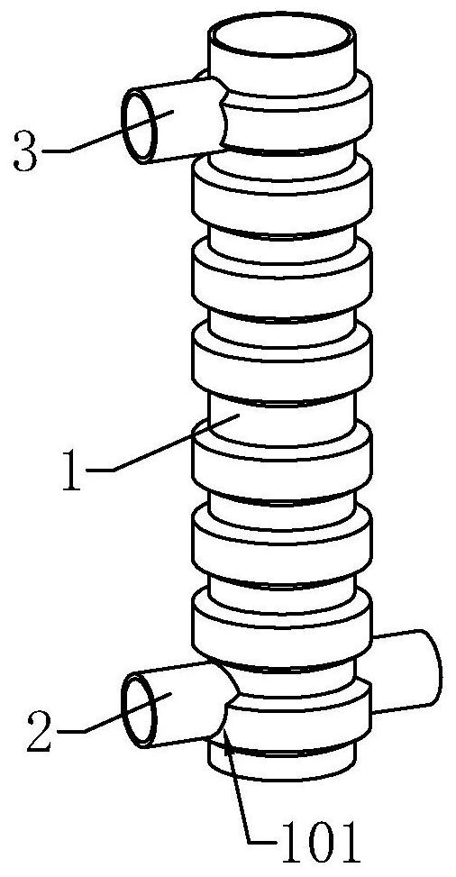
[0037] See attached figure 1 What is claimed is a grouted metal bellows for steel bar anchoring, comprising a bellows section open at both ends, having a wall thickness of at least 2mm, a rib height of at least 3mm, and a wave pitch of 32±2mm. According to the actual needs of different projects, the inner diameter of the bellows section is available in various specifications such as 65mm and 80mm.
[0038] The bellows section is provided with a grouting hole and a grouting hole perpendicular to the axial direction on the pipe wall close to the opening at both ends, and the grouting hole and the grouting hole are respectively vertically fixed with a grouting pipe and a grouting pipe; the opening of the grouting pipe and the grouting pipe At least 20mm inside diameter. At the same time, the net distance between the grouting hole and the adjacent end of the bellows section is at least 220mm, and the net distance between the grouting hole and the adjacent end of the bellows secti...
Embodiment 2
[0041] See attached figure 2 , a grouting metal bellows for steel bar anchoring, which is basically the same in structure as in Example 1, the difference being that one end of the bellows section is open, and the other end is welded and fixed with a sealing plate. Specifically, the sealing plate can be arranged at the end where the grouting hole is located, and can effectively seal the corresponding port of the bellows section.
[0042] The working principle of this embodiment is: in actual construction, the metal bellows is suitable for the assembly of pier columns and caps. Specifically, the metal bellows building is fixed in the cap; the upper end of the bellows section where the sealing plate is located is at the bottom, and the opening end is at the top, which is used to insert the main reinforcement on the pier column.
Embodiment 3
[0044] See attached image 3 , a grouting metal bellows for steel bar anchoring, its structure is basically the same as that of Example 1, the difference is that: the grouting hole runs through the bellows section along the direction vertical to the axial direction of the bellows section, and the grouting pipe is pierced along the grouting hole in the The bellows section is welded and fixed with the bellows section. In this way, the openings at both ends of the grouting pipe are respectively located on both radial sides of the corrugated pipe section, and respectively constitute an opening for grouting. At the same time, if Figure 4 As shown, the wall of the grouting pipe located inside the corrugated pipe section is also provided with a number of grouting notches evenly distributed around the circumference. Moreover, in order to ensure the grouting efficiency, the grouting pipe can be set in a structure with thin ends and a thick middle, that is, the inner diameter of the ...
PUM
| Property | Measurement | Unit |
|---|---|---|
| thickness | aaaaa | aaaaa |
Abstract
Description
Claims
Application Information
 - R&D Engineer
- R&D Manager
- IP Professional
- Industry Leading Data Capabilities
- Powerful AI technology
- Patent DNA Extraction
Browse by: Latest US Patents, China's latest patents, Technical Efficacy Thesaurus, Application Domain, Technology Topic, Popular Technical Reports.
© 2024 PatSnap. All rights reserved.Legal|Privacy policy|Modern Slavery Act Transparency Statement|Sitemap|About US| Contact US: help@patsnap.com