
Liquid crystal display device and alignment film material thereof

a technology of liquid crystal display and alignment film, which is applied in the direction of non-fibrous pulp addition, instruments, transportation and packaging, etc., can solve the problem that the effective method of improving alignment orderliness has not yet been discovered, and achieve the effect of increasing the order parameter (op) and increasing the anchoring strength

Active Publication Date: 2012-11-29
JAPAN DISPLAY INC
View PDF1 Cites 5 Cited by
  • Summary
  • Abstract
  • Description
  • Claims
  • Application Information

AI Technical Summary

Benefits of technology

[0006]In optical alignment processing in the related art, image burn called an AC afterimage occurs more easily as compared with rubbing. The AC afterimage is an afterimage generated because an initial alignment direction is deviated from a direction at the time of first manufacturing of the liquid crystal display device when the liquid crystal display device operates over a long time. The AC afterimage is irreversible and irrecoverable.
[0007]The AC afterimage can be improved by (1) improvement of alignment orderliness of an alignment film, (2) improvement of mechanical strength using modulus of elasticity and hardness of the alignment film as parameters, and (3) improvement of affinity between the alignment film and liquid crystals. Among them, improvement of alignment orderliness of the alignment film is particularly effective in reducing the AC afterimage.
[0011]According to embodiments of the present invention, since an order parameter (OP) can be increased and an anchoring strength can be increased in an optical alignment film, a liquid crystal display device having the optical alignment film suppressing an AC afterimage can be implemented.

Problems solved by technology

However, in the optical alignment method, the effective method for improving the alignment orderliness has not been discovered.

Method used


Image

  • Liquid crystal display device and alignment film material thereof
  • Liquid crystal display device and alignment film material thereof
  • Liquid crystal display device and alignment film material thereof

Examples


example 1

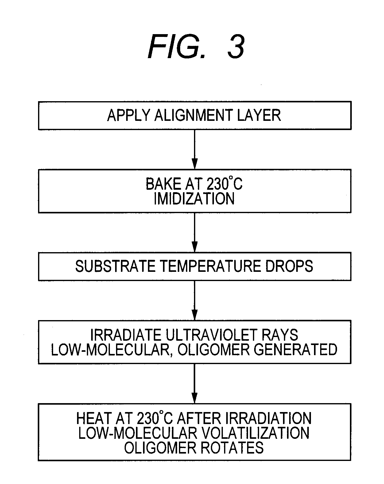
[0034]FIG. 3 is a diagram illustrating a process of forming an alignment film subjected to optical alignment processing. The process of FIG. 3 is common to the TFT substrate, and the opposed substrate. The alignment film is applied to the TFT substrate with the pixel electrode or the opposite substrate with the overcoat layer in FIG. 1. The alignment film may be applied by using a spin coating method, an inkjet method, a spray coating method, or a rod coating method.

[0035]The alignment film material contains an alignment material acquired by esterifying dehydrated condensate of paraphenyldiamine represented by (Chem. 1) and 1,3-dimethyl cyclobutane tetracarboxylic acid dianhydride represented by (Chem. 3) as well as and an alignment material acquired by esterifying dehydrated condensate of 1,2-bis(4-aminophenyl)ethane represented by (Chem. 2) and 1,3-dimethyl cyclobutane tetracarboxylic acid dianhydride represented by (Chem. 3) at a weight ratio of 1:1.

[0036]The applied alignment fi...


PUM

PropertyMeasurementUnit
thicknessaaaaaaaaaa
wavelengthaaaaaaaaaa
total weightaaaaaaaaaa

Abstract

To form an optical alignment film having large anchoring strength and suppress an AC afterimage of a liquid crystal display device, in a liquid crystal display device of an IPS mode. In an alignment film material subjected to optical alignment processing, polyimide which becomes a rigid high molecule and polyimide which becomes a flexible high molecule are mixed and used. The material of the present invention can easily rotate oligomer after irradiating polarized ultraviolet rays and improve a UV-absorbed two-color ratio of an alignment film. Accordingly, an anchoring strength for liquid crystals by the alignment film is large to suppress an AC afterimage.

Description

CLAIM OF PRIORITY[0001]The present application claims priority from Japanese Patent Application JP 2011-114470 filed on May 23, 2011, the content of which is hereby incorporated by reference into this application.FIELD OF THE INVENTION[0002]The present invention relates to a liquid crystal display device, and more particularly, to a liquid crystal display device that grants an alignment control capability by irradiating light to an alignment film.BACKGROUND OF THE INVENTION[0003]In a liquid crystal display device, a TFT substrate in which a pixel electrode and a thin film transistor (TFT) are formed in matrices and an opposed substrate where a color filter is formed at a place corresponding to the pixel electrode of the TFT substrate is installed to be opposed to the TFT substrate, and liquid crystals are interposed between the TFT substrate and the opposed substrate. An image is formed by controlling light transmittance by liquid crystal molecules for each pixel.[0004]Since the liq...

Claims


Application Information

Patent Timeline
Patent Type & Authority Applications(United States)
IPC IPC(8): G02F1/1337C09D5/00
CPCG02F1/133788C09K19/56Y10T428/1018Y10T428/1023Y10T428/1005G02F1/133711C09K2323/02C09K2323/025C09K2323/027C08G73/10C08L79/08G02F1/1337
Inventor UCHINO, SHOICHIKUNIMATSU, NOBORU
Owner JAPAN DISPLAY INC
Learn More