Machining grinding device
A grinding device and mechanical processing technology, which is applied in the direction of grinding drive device, grinding/polishing safety device, metal processing equipment, etc., can solve the problems of increased work complexity and manpower consumption, so as to reduce complexity and improve efficiency , to avoid the flipping effect
- Summary
- Abstract
- Description
- Claims
- Application Information
AI Technical Summary
Problems solved by technology
Method used
Image
Examples
Embodiment 1
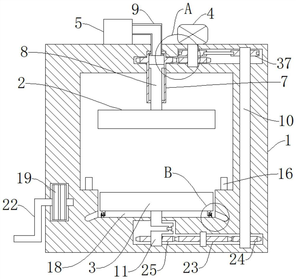
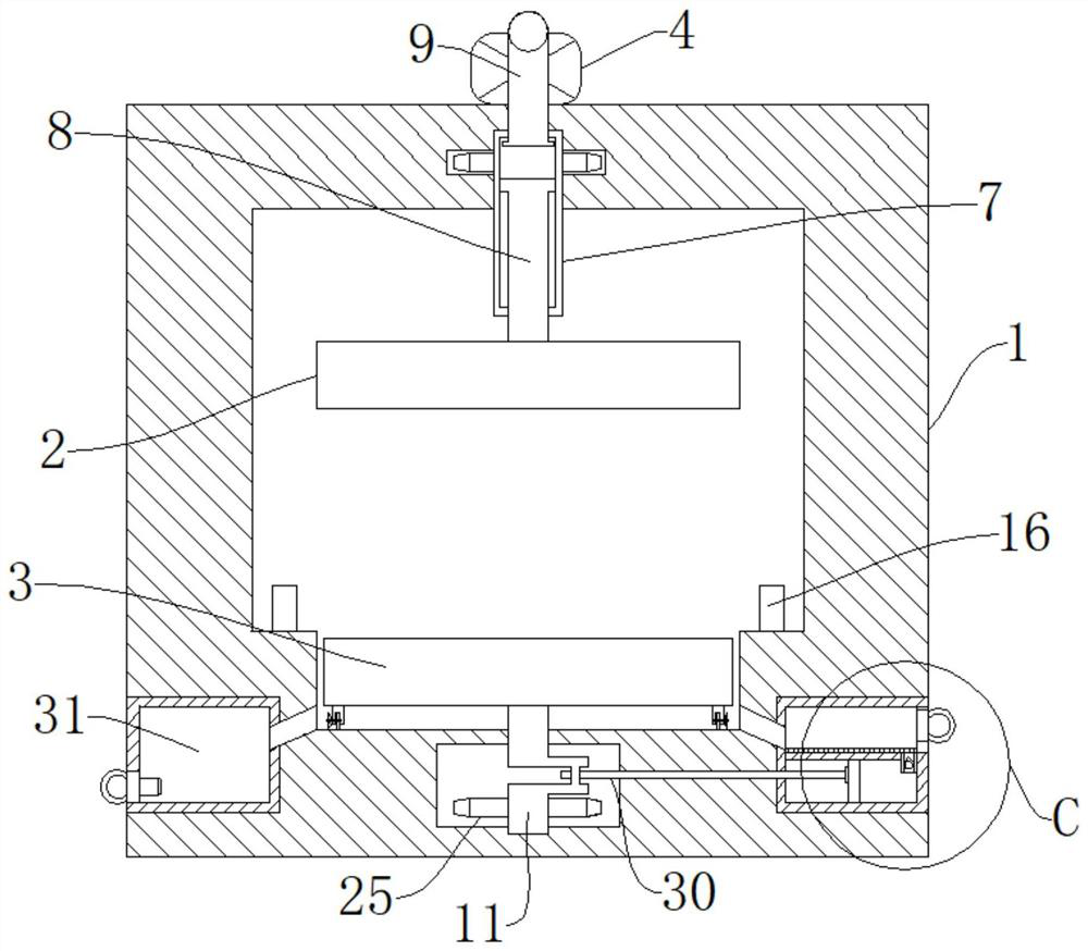
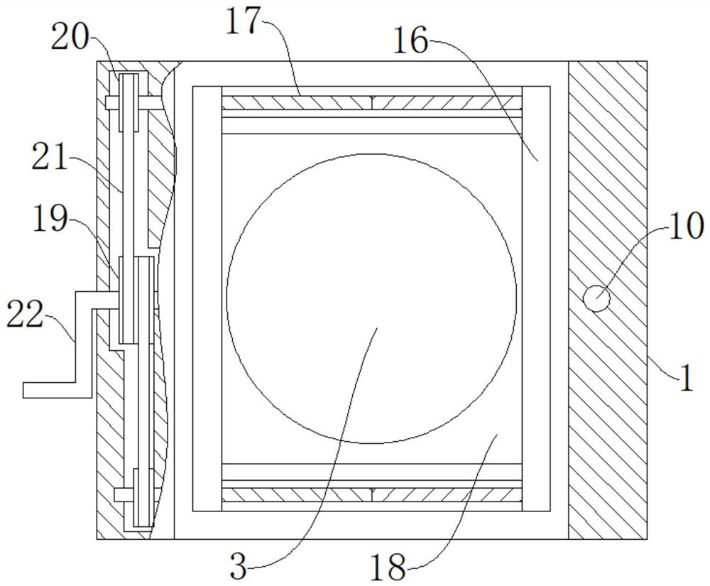
[0035] refer to Figure 1-9 , a mechanical processing grinding device, including a working body 1, and also includes an upper grinding wheel 2, a lower grinding wheel 3, the upper end of the working body 1 is rotatably connected with a driving shaft 15 and a sliding cylinder 7, and the top end of the working body 1 is connected with a drive motor 4, The hydraulic pump 5, the output end of the driving motor 4 is fixedly connected with the driving shaft 15, the upper end of the sliding cylinder 7 is rotatably connected with a liquid pipe 9, and the end of the liquid pipe 9 away from the sliding cylinder 7 is connected with the hydraulic pump 5, and the sliding cylinder 7 is connected with a The first connecting rod 8, the end of the first connecting rod 8 away from the sliding cylinder 7 is fixedly connected with the upper grinding wheel 2, the lower end of the working body 1 is provided with a collection tank 18, and the second driven shaft 11 is rotatably connected in the colle...
Embodiment 2
[0042] refer to Figure 1-9 , a mechanical processing grinding device, which is basically the same as that of Embodiment 1, furthermore: the lower end of the working body 1 is symmetrically slidably connected with a clamping plate 16, the clamping plate 16 is matched with the lower grinding wheel 3, and the lower end of the working body 1 is symmetrical Rotationally connected with a two-way screw rod 17, the two-way screw rod 17 is threadedly connected with the clamping plate 16, and one side of the working body 1 is rotatably connected with a second driving pulley 19, and one end of the two-way screw rod 17 near the second driving pulley 19 is fixedly connected There is a second driven pulley 20, and a transmission belt 21 is connected in pairs on the second driving pulley 19, and the end of the transmission belt 21 away from the second driving pulley 19 is connected with the second driven pulley 20, so that the workpiece is fixed , which is conducive to the smooth progress o...
Embodiment 3
[0044] refer to Figure 1-9 , a mechanical processing grinding device, which is basically the same as that of Embodiment 1, furthermore: the bottom end of the lower grinding wheel 3 is fixedly connected with a plurality of sets of support blocks 27, and the support blocks 27 are rotatably connected with connecting shafts, and the connecting shafts are fixedly connected Roller 28 is arranged, and one end of connecting shaft away from support block 27 is fixedly connected with rotating fan blade 29, which is convenient for abrasive debris to be blown in the annular water tank 26, and makes the lower grinding wheel rotate 3 more steadily while moving.
PUM
 Abstract
Description
Claims
Application Information
 - R&D
- Intellectual Property
- Life Sciences
- Materials
- Tech Scout
- Unparalleled Data Quality
- Higher Quality Content
- 60% Fewer Hallucinations
Browse by: Latest US Patents, China's latest patents, Technical Efficacy Thesaurus, Application Domain, Technology Topic, Popular Technical Reports.
© 2025 PatSnap. All rights reserved.Legal|Privacy policy|Modern Slavery Act Transparency Statement|Sitemap|About US| Contact US: help@patsnap.com


