
Diesel machine waste gas purification process

A purification process and exhaust gas purification technology, applied in the direction of machines/engines, gas treatment, mechanical equipment, etc., can solve the problems of incomplete combustion of fuel mixture, unfavorable small enterprises to put into use, high operating costs, etc., to achieve ingenious structural design, The effect of low input cost and easy popularization

Inactive Publication Date: 2020-12-11
沈高金
View PDF0 Cites 0 Cited by
  • Summary
  • Abstract
  • Description
  • Claims
  • Application Information

AI Technical Summary

Problems solved by technology

[0002] During the operation of diesel engines, due to wear of piston rings and cylinder liners, changes in the shape of the combustion chamber, poor work of the fuel injectors, and excessive fuel supply, etc., black smoke will appear in the exhaust. The main component is NO x And particulate soot, mainly caused by poor formation of fuel mixture or incomplete combustion, etc., its discharge into the atmosphere will seriously pollute the atmosphere and cause irreversible environmental problems
Nowadays, most factories use high-temperature catalytic reduction to reduce NO x Reduction into non-polluting nitrogen, due to the high reaction temperature and the need for a catalyst, the investment in equipment is large, and the operating cost is large, which is not conducive to small enterprises starting to use

Method used


Image

  • Diesel machine waste gas purification process
  • Diesel machine waste gas purification process
  • Diesel machine waste gas purification process

Examples


Embodiment 1

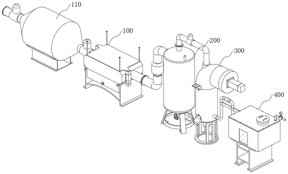
[0082] The invention provides a multi-stage purification equipment for purifying exhaust gas released by diesel engines, comprising the following steps:

[0083] 1. Waste gas combustion purification stage:

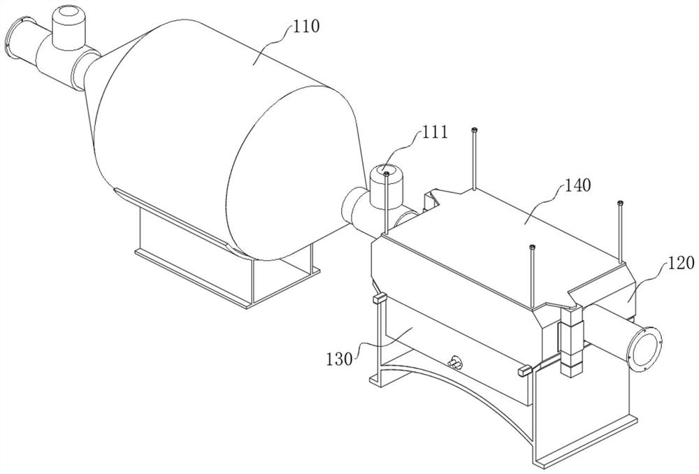
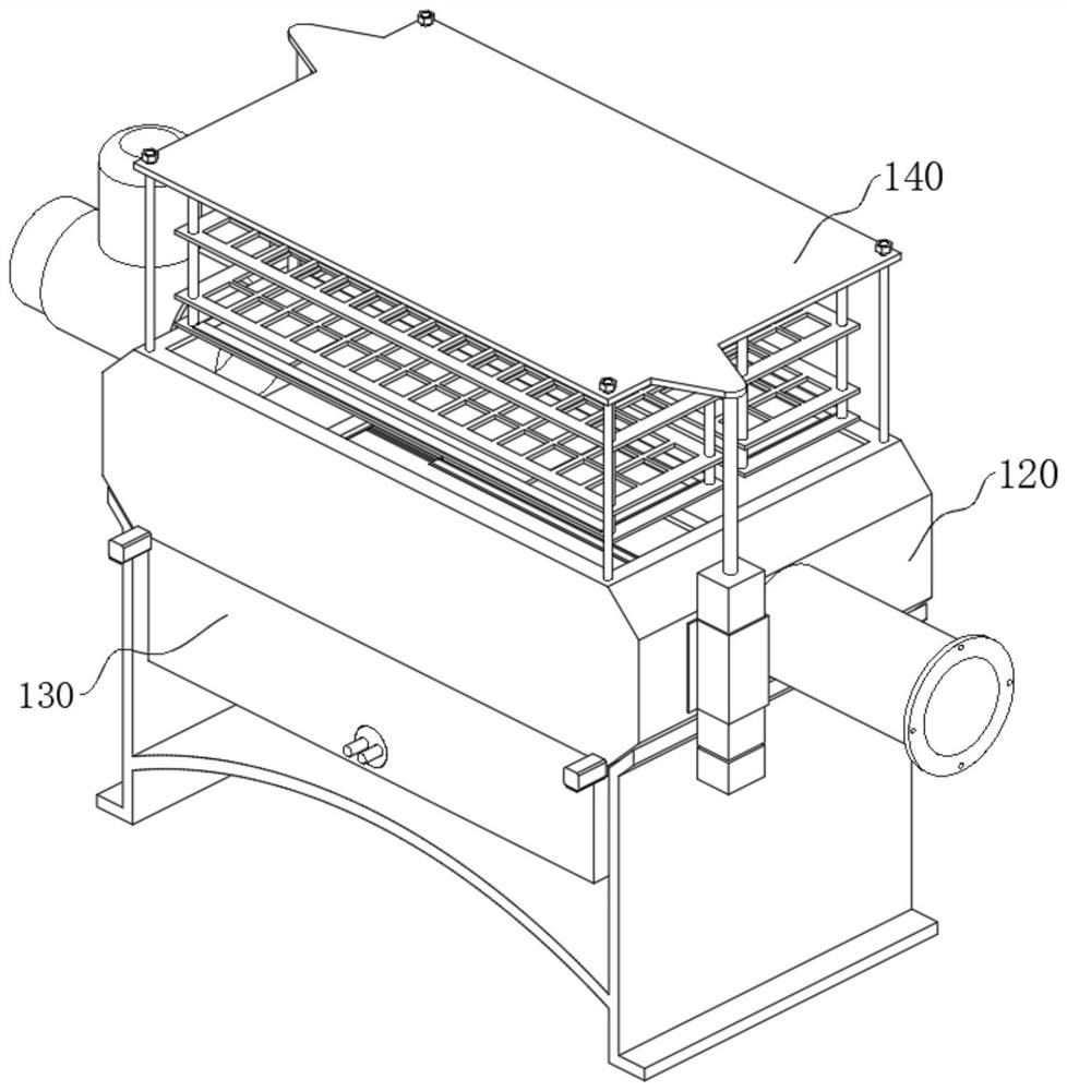
[0084] S1, first start the electric cylinder 150 of the exhaust gas purification equipment of the diesel engine to drive the charcoal rack 140 to rise until the charcoal plate 142 is exposed, and then put some charcoal on the charcoal plate 142 at equal intervals;

[0085] S2. Restart the electric cylinder 150 to reset the piston rod, and the charcoal rack 140 falls into the combustion box 120 under the force of its own weight;

[0086] S3, then connect the power supply of the electric heating tube 180 to make it work to generate heat, enter the combustion box 120 through the heat transfer port 122, and then bake the charcoal to turn red;

[0087] S4, turn off the power supply of the electric heating tube 180, then start the forward and reverse motor 170 to make it work i...


PUM


Abstract

The invention discloses a diesel engine waste gas purification process. The diesel engine waste gas purification process comprises the following steps that firstly, waste gas just discharged by a diesel engine is re-combusted and decomposed through a combustion box, then enters a filter tower to react with an alkaline solution to generate precipitates, then is adsorbed and purified through a molecular sieve under the pressure action of a push cylinder, and finally is denitrified by denitrifying bacteria in a denitrification box to generate nitrogen to be discharged. According to the diesel engine waste gas purification process, the waste gas is discharged into the combustion box and is subjected to secondary combustion decomposition, so that the concentration of carbon particles and combustible particles in the waste gas is reduced, then the waste gas is discharged into the filter tower and reacts with the alkaline solution in the filter tower to generate the precipitates, the waste gas are massively purified, then the gas is adsorbed by the molecular sieve and selectively passes through under the pressure action of the push cylinder, then the gas is dissolved into the alkaline solution in the denitrification box and reacts with the denitrifying bacteria to generate the nitrogen, so that thorough purification is achieved, the waste gas is purified step by step through the structure, equipment purification pressure can be relieved, the practicability is high, and the popularization is easy.

Description

technical field [0001] The invention relates to the technical field of diesel engine exhaust gas purification, in particular to a purification process for diesel engine exhaust gas. Background technique [0002] During the operation of diesel engines, due to wear of piston rings and cylinder liners, changes in the shape of the combustion chamber, poor work of the fuel injectors, and excessive fuel supply, etc., black smoke will appear in the exhaust. The main component is NO x And particulate soot, mainly caused by poor formation of fuel mixture or incomplete combustion. Its emission into the atmosphere will seriously pollute the atmosphere and cause irreversible environmental problems. Nowadays, most factories use high-temperature catalytic reduction to reduce NO x Reduction into non-polluting nitrogen, due to the high reaction temperature and the need for a catalyst, the investment in equipment is large, and the operating cost is large, which is not conducive to small ent...

Claims


Application Information

Patent Timeline
Patent Type & Authority Applications(China)
IPC IPC(8): F01N3/26F01N3/08B01D53/56B01D53/75B01D53/78B01D53/84B01D53/02
CPCB01D53/02B01D53/56B01D53/75B01D53/78B01D53/84B01D2251/95B01D2253/108B01D2253/116B01D2258/012F01N3/08F01N3/0807F01N3/26Y02A50/20
Inventor 沈高金
Owner 沈高金
Learn More