
Special machine tool for machining chutes of zigzag labyrinth sealing part

A technology of labyrinth seal and special machine tool, applied in the direction of metal processing machinery parts, metal processing equipment, manufacturing tools, etc., can solve the problems of low processing efficiency, blind spots, difficult operation, etc., to improve processing efficiency, avoid mechanical errors, The effect of machining accuracy and quality assurance

Active Publication Date: 2020-12-08
滁州佳庆数控有限责任公司
View PDF7 Cites 3 Cited by
  • Summary
  • Abstract
  • Description
  • Claims
  • Application Information

AI Technical Summary

Problems solved by technology

[0002] Existing two-axis CNC lathes can only process radial seal grooves and axial seal grooves, but cannot process radial slanted labyrinth grooves. At present, only slanted labyrinth grooves can be reserved in CNC machine tools. Then change to ordinary lathe processing to complete
[0003] The above-mentioned processing methods mainly have the following disadvantages: 1. The processing method of two clampings leads to low processing efficiency and difficult operation; 2. The waste chips generated during the turning process cannot be automatically discharged in the chute, and the cutting fluid is usually sprayed. to flush out the waste chips, but as the machining depth of the chute gradually increases, the cutting fluid at the liquid outlet will have a blind area relative to the inside of the groove, resulting in the inability to effectively discharge the waste chips

Method used


Image

  • Special machine tool for machining chutes of zigzag labyrinth sealing part
  • Special machine tool for machining chutes of zigzag labyrinth sealing part
  • Special machine tool for machining chutes of zigzag labyrinth sealing part

Examples


Embodiment Construction

[0022] In order to make the technical means, creative features, goals and effects achieved by the present invention easy to understand, the present invention will be further described below in conjunction with specific embodiments.

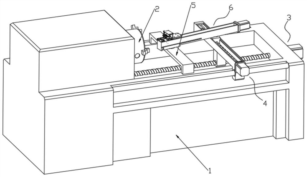
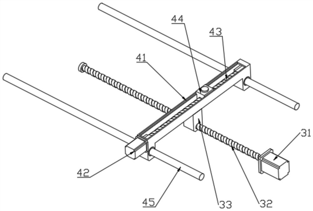
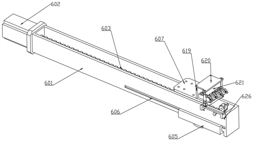
[0023] Such as Figure 1 to Figure 6 As shown, a special machine tool for machining inclined grooves of zigzag labyrinth sealing parts, including a body 1 and a chuck 2, the chuck 2 is installed on the body 1, and a first feeding mechanism is installed on the body 1 3. It is used to process the axial groove on the workpiece clamped on the chuck 2. The second feeding mechanism 4 is also installed on the body 1 to perform radial groove processing on the workpiece clamped on the chuck 2. For groove processing, a support frame 5 is fixedly arranged on the fuselage 1, a third feed mechanism 6 is installed on the upper end of the second feed mechanism 4, and the third feed mechanism 6 is rotatably arranged on the upper end of the support frame 5 , and ...


PUM


Abstract

The invention relates to the technical field of machine tool automation equipment, and discloses a special machine tool for machining chutes of a zigzag labyrinth sealing part. The special machine tool comprises a machine body and a chuck, the chuck is installed on the machine body, a first feeding mechanism is installed on the machine body and used for machining axial grooves in a workpiece clamped on the chuck, and a second feeding mechanism is further installed on the machine body and used for machining radial grooves in the workpiece clamped on the chuck. By arranging a third feeding mechanism and adopting a tool arrangement layout manner in the third feeding mechanism, machining of straight grooves, the chutes and the axial grooves can be completed only by clamping the workpiece at atime; the slotting angle can be automatically adjusted according to actual production requirements, and a plurality of turning tools are synchronously fed for slotting, so that the machining efficiency is greatly improved; and by arranging a worm wheel in a second mounting frame and arranging a cam on a rotating shaft, scraps generated in the turning process can be dynamically removed, and it is guaranteed that synchronous cutting of the multiple turning tools is effectively conducted.

Description

technical field [0001] The invention relates to the technical field of machine tool automation equipment, in particular to a special machine tool for machining inclined grooves of zigzag labyrinth sealing parts. Background technique [0002] Existing two-axis CNC lathes can only process radial seal grooves and axial seal grooves, but cannot process radial slanted labyrinth grooves. At present, only slanted labyrinth grooves can be reserved in CNC machine tools. Then change to complete by ordinary lathe processing. [0003] The above-mentioned processing methods mainly have the following disadvantages: 1. The processing method of two clampings leads to low processing efficiency and difficult operation; 2. The waste chips generated during the turning process cannot be automatically discharged in the chute, and the cutting fluid is usually sprayed. However, as the machining depth of the chute gradually increases, the cutting fluid at the liquid outlet will have a blind area re...

Claims


Application Information

Patent Timeline
Patent Type & Authority Applications(China)
IPC IPC(8): B23B5/00B23B21/00B23Q3/12B23Q5/40
CPCB23B5/00B23Q3/00B23Q3/12B23Q5/40
Inventor 冯善刚
Owner 滁州佳庆数控有限责任公司
Learn More