Film piezoelectric acoustic wave filter and manufacturing method thereof
A piezoelectric sound wave and filter technology, applied in the direction of electrical components, impedance networks, etc., can solve problems such as low reliability and poor cover stability, and achieve the effects of reduced structural strength, reduced volume, and reduced leakage loss
- Summary
- Abstract
- Description
- Claims
- Application Information
AI Technical Summary
Problems solved by technology
Method used
Image

Examples
Embodiment 1
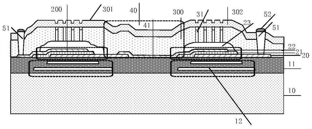
[0042] An embodiment of the present invention provides a thin-film piezoelectric acoustic wave filter, figure 1 It is a structural schematic diagram of a thin-film piezoelectric acoustic wave filter according to an embodiment of the present invention, in which only two acoustic wave resonator units are shown in the figure, specifically the number of acoustic wave resonator units in each filter and the electrical connections between them The method is specifically set according to the requirements of the filter itself.
[0043] Please refer to figure 1 , the thin-film piezoelectric acoustic wave filter includes:
[0044] First substrate; a plurality of acoustic wave resonator units 200 placed on the first substrate; the acoustic wave resonator unit 200 is the smallest resonance unit, and each acoustic wave resonator unit 200 includes a piezoelectric induction sheet 21 for A first electrode and a second electrode opposite to each other that apply a voltage to the piezoelectric...
Embodiment 2
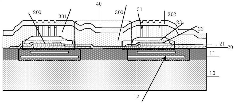
[0064] refer to figure 2 , figure 2 Take the connection of the piezoelectric induction plates 21 of two adjacent piezoelectric resonators as an example.
[0065] In Embodiment 2, the piezoelectric induction plates 21 of at least some of the adjacent acoustic wave resonator units 200 in the filter are connected together, and the projection of the first cavity 23 on the acoustic wave resonator unit 200 Part of the boundary encloses the boundary of the effective area of the connected piezoelectric induction plates 21 . When the piezoelectric induction sheets 21 of a plurality of acoustic wave resonator units are connected together, the upper electrode 22 and the lower electrode 20 of each acoustic wave resonator unit form an effective working area in the overlapping area perpendicular to the direction of the piezoelectric induction sheet 21. Area. The isolation part 40 between the adjacent first cavities 23 makes the acoustic impedance mismatch between the effective workin...
Embodiment 3
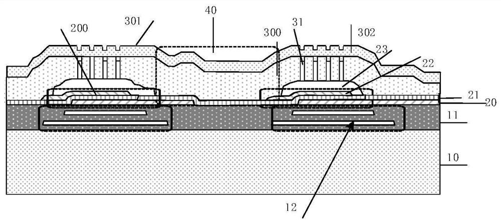
[0067] see image 3 , in this embodiment, the piezoelectric induction plates 21 of all the acoustic wave resonator units 200 in the filter are connected together, and the boundary area of the projection of the first cavity 23 on the acoustic wave resonator unit 200 becomes the boundary of the effective working area of the acoustic wave resonator unit 200. The isolation portion 40 between the adjacent first cavities 23 makes the acoustic impedance mismatch between the effective working area and the invalid working area, so as to solve the shear wave leakage caused by the connection of the piezoelectric induction plates 21 together. In this way, the piezoelectric layer does not need to be patterned to form the piezoelectric induction sheet of each acoustic wave resonator unit, which simplifies the process. It should be understood that when the overall boundary of the first cavity coincides with the overall boundary of the effective working area, the size of the first cavity...
PUM
| Property | Measurement | Unit |
|---|---|---|
| Thickness | aaaaa | aaaaa |
| Total thickness | aaaaa | aaaaa |
| Thickness | aaaaa | aaaaa |
Abstract
Description
Claims
Application Information
 - R&D
- Intellectual Property
- Life Sciences
- Materials
- Tech Scout
- Unparalleled Data Quality
- Higher Quality Content
- 60% Fewer Hallucinations
Browse by: Latest US Patents, China's latest patents, Technical Efficacy Thesaurus, Application Domain, Technology Topic, Popular Technical Reports.
© 2025 PatSnap. All rights reserved.Legal|Privacy policy|Modern Slavery Act Transparency Statement|Sitemap|About US| Contact US: help@patsnap.com