Plate heat exchanger adopting liquid cooling

A plate heat exchanger, liquid cooling technology, applied in the direction of heat exchanger type, heat exchanger shell, indirect heat exchanger, etc., can solve the pressure drop increase, the heat dissipation improvement effect is small, and the heat dissipation effect cannot be considered alone, etc. problem, to achieve the effect of large temperature difference, reduction of flow dead zone, and strong cooling capacity

Active Publication Date: 2020-12-04
CHINA NORTH VEHICLE RES INST
View PDF9 Cites 0 Cited by
  • Summary
  • Abstract
  • Description
  • Claims
  • Application Information

AI Technical Summary

Problems solved by technology

However, this design cannot only consider the heat dissipation effect, but also from the perspective of system economy, try to avoid the situation where the pressure drop increases sharply after adding fins and the heat dissipation improvement effect is minimal

Method used


Image

  • Plate heat exchanger adopting liquid cooling
  • Plate heat exchanger adopting liquid cooling
  • Plate heat exchanger adopting liquid cooling

Examples


Embodiment Construction

[0042] The present disclosure will be further described below in conjunction with the accompanying drawings and specific embodiments.

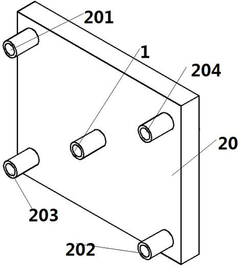
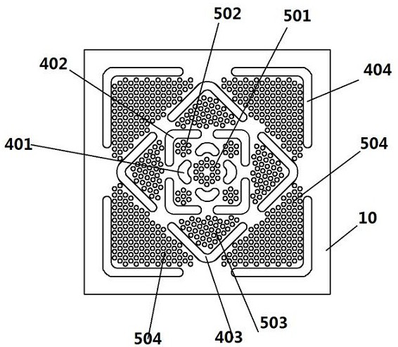
[0043] like Figure 1-4 A liquid-cooled plate heat exchanger with a square structure is shown, including a bottom plate 10 and a cover plate 20. The bottom plate 10 and the cover plate 20 are square structures, and the cover plate 20 and the bottom plate 10 are assembled together to form a square cavity. The cooling liquid (preferably water) flows in the cavity, and baffles 401-404 and ribs 501-504 are arranged on the bottom plate 10, and the baffles include the first baffle 401 located in the center of the bottom plate, surrounded by the second A second baffle 402 outside the first baffle 401, a third baffle 403 outside the second baffle 402, and a fourth baffle 404 outside the third baffle 403;

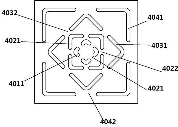
[0044] As preferred, such as Figure 1-3 As shown, the first baffle 401 includes four pieces, and each first baffle 401 includes two baffle walls...


PUM


Abstract

The invention provides a plate heat exchanger adopting liquid cooling. The plate heat exchanger comprises a bottom plate and a cover plate, wherein the bottom plate and the cover plate are of a squarestructure, the cover plate and the bottom plate are assembled together to form a square cavity, cooling liquid flows in the cavity, and baffle plates and fins are arranged on the bottom plate; the baffle plates include first baffle plates located at the center of the bottom plate, second baffle plates surrounding the first baffle plates, third baffle plates surrounding the second baffle plates and fourth baffle plates surrounding the third baffle plates; and a plurality of fins are arranged in the space defined by the first baffle plates, a plurality of fins are arranged between the second baffle plates and the first baffle plates, a plurality of fins are arranged between the second baffle plates and the third baffle plates, and a plurality of fins are arranged between the third baffle plates and the fourth baffle plates. According to the plate heat exchanger of the novel structure, through cooperation of the multiple layers of fins and the baffle plates, the heat exchange efficiencycan be further improved, and heat transfer is enhanced.

Description

technical field [0001] The invention belongs to the technical field of heat exchangers, and in particular relates to a plate heat exchanger in which a flow guiding structure and fins are combined. Background technique [0002] The plate heat exchanger is the heat exchanger with the highest heat exchange efficiency among all kinds of heat exchangers at present. It has the advantages of small space occupation and convenient installation and disassembly. It is composed of stamped concave-convex stainless steel plates. The concave-convex lines between two adjacent plates are combined at 180 degrees. Therefore, the concave-convex ridges between the two plates of the plate heat exchanger form staggered contact points, and the contact points After being combined by vacuum welding, the high-pressure staggered flow structure of the plate heat exchanger is formed. These staggered flow structures make the hot and cold liquids in the plate heat exchanger generate strong turbulence and a...

Claims


Application Information

Patent Timeline
IPC IPC(8): F28D9/00F28F3/06F28F9/22F28F9/24F28F27/02
CPCF28D9/0037F28F3/06F28F9/22F28F9/24F28F27/02
Inventor 张佳卉杨勇刘洋赵春伟石军曹元福李源浩刘江权籍力
Owner CHINA NORTH VEHICLE RES INST
Why Eureka
Try Eureka