Flue gas white smoke removal device
A flue gas and chimney technology, used in the field of flue gas purification, can solve problems such as pipe blockage and dust condensation, and achieve the effects of preventing blockage, bearing high temperature and high pressure, and improving whitening efficiency
- Summary
- Abstract
- Description
- Claims
- Application Information
AI Technical Summary
Problems solved by technology
Method used
Image


Examples
Embodiment 1
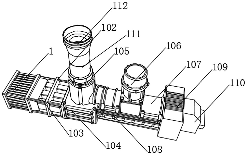
[0034] see Figure 1-5 , the present invention provides the following technical solutions: a flue gas dewhitening device, comprising a desulfurization box 1, a thermostat 101 is fixedly installed on the outside of the desulfurization box 1, a fixed frame 102 is installed on one side of the desulfurization box 1, and the inside of the fixed frame 102 Install the flue gas dredging channel 103, one end of the flue gas dredging channel 103 is fixedly connected to one side of the desulfurization box 1, the other end of the flue gas dredging channel 103 is fixedly connected to the bottom end of the heat exchanger 104, and one side of the heat exchanger 104 is fixed Connection, the top of the heat exchanger 104 is fixedly installed with a cooler 106, one side of the cooler 106 is fixedly connected with one end of the delivery pipe 107, the bottom end of the fixed pipe is fixed with a support seat 108, and the top of the support seat 108 is fixed with a condensing A fan 110 is fixedly...
Embodiment 2
[0046] see Figure 1-5 , is different from Example 1 in that the atomized filter plate is made of the following raw materials in parts by weight: 43 parts of copper powder, 11 parts of tin powder, 12 parts of zirconium silicate, 5 parts of aluminum oxide, and 5 parts of zinc oxide , 11 parts of chromium powder, 14 parts of coral fossils, 15 parts of tourmaline, 15 parts of dysprosium carbonate, 11 parts of graphene, 10 parts of aluminum oxide, 7 parts of potassium oxide, 3 parts of zirconia, 3 parts of oleic acid and polyacrylic acid Sodium 11 parts. A preparation method for an atomized filter plate, comprising the following steps:
[0047] 1) Weigh 43 parts of copper powder, 11 parts of tin powder, 12 parts of zirconium silicate, 5 parts of aluminum oxide, 5 parts of zinc oxide, 11 parts of chromium powder, 14 parts of coral fossils, 15 parts of tourmaline, and 11 parts of graphene 10 parts of Al2O3, 7 parts of Potassium Oxide, and 3 parts of Zirconia were added to the ball...
experiment example
[0054] Experimental object: use fine steel atomization filter plate, copper alloy atomization filter plate and cermet atomization filter plate of the present invention for comparison. Experimental requirements: the above-mentioned common stainless steel atomizing filter plate, copper alloy atomizing filter plate and the cermet atomizing filter plate of this application have the same thickness and the same area.
[0055] Experimental method: by carrying out temperature resistance test, wear test and chemical corrosion test on fine steel atomization filter plate, copper alloy atomization filter plate and the cermet atomization filter plate of the application, in this experimental example, the temperature resistance test is Low temperature and high temperature test, chemical corrosion adopts sulfuric acid dripping to test the surface of the test object.
[0056] The specific results are shown in the table below:
[0057]
[0058] In conjunction with the above table, comparing...
PUM
 Abstract
Description
Claims
Application Information
 - R&D
- Intellectual Property
- Life Sciences
- Materials
- Tech Scout
- Unparalleled Data Quality
- Higher Quality Content
- 60% Fewer Hallucinations
Browse by: Latest US Patents, China's latest patents, Technical Efficacy Thesaurus, Application Domain, Technology Topic, Popular Technical Reports.
© 2025 PatSnap. All rights reserved.Legal|Privacy policy|Modern Slavery Act Transparency Statement|Sitemap|About US| Contact US: help@patsnap.com