
Fluidic devices and methods for multiplex chemical and biochemical reactions

a technology of biochemical reactions and fluidic devices, which is applied in the field of fluidic devices for carrying out multiplex chemical or biochemical reactions and performing multiplex chemical and/or biochemical assays, can solve the problems of inadequate assay specificity, inability to meet the needs of many applications, and inability to meet the needs of multiple applications

Inactive Publication Date: 2011-06-16
LC SCI LC
View PDF7 Cites 115 Cited by
  • Summary
  • Abstract
  • Description
  • Claims
  • Application Information

AI Technical Summary

Benefits of technology

[0150]Another advantage of the present invention is the ease of bubble and particle removal from the disclosed microfluidic array devices. For most of applications, the bypass channels 231 and 232 of FIG. 2 have significantly larger cross-sections than that of inlet and outlet conduits 221 and 222. These bypass channels, therefore, provide easier paths for particles and bubbles to be flushed out the device.
[0151]In another aspect of this invention, the cover plate 140 is a flat and opaque or translucent plate. The optical transparency of the cover plate 140 is not necessary when a chamber array device shown in FIG. 1A is to be used as a multiplexing reactor for non-photochemical reactions and a non-photo-detection based assay device. Non-photochemical reactions include electrochemical reactions, which have been described by Montgomery in U.S. Pat. No. 6,444,111. By adding electrodes to the chamber array device, one skilled in the art of electrochemistry may perform multiplexing synthesis reactions. An exemplary non-photo-detection based assay is the electron transfer based nucleic acid detection, which is described by Meade et al. in U.S. Pat. No. 6,013,459 and the references therein. By adding electrodes in a chamber array device, one skilled in the art of molecular electronic detection may perform multiplexing nucleic acid and other molecular detection.
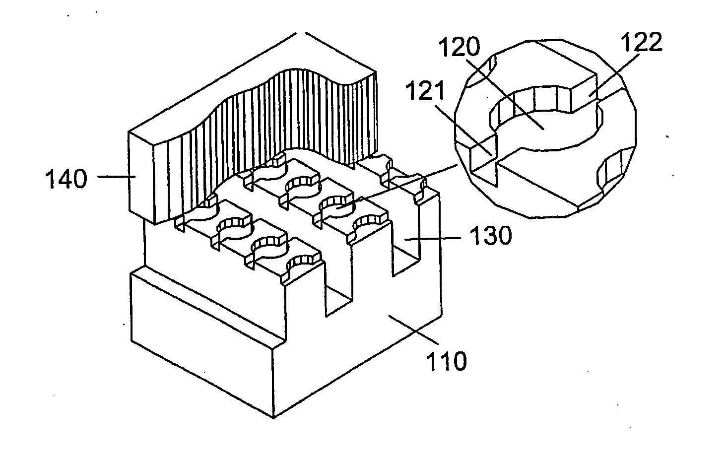
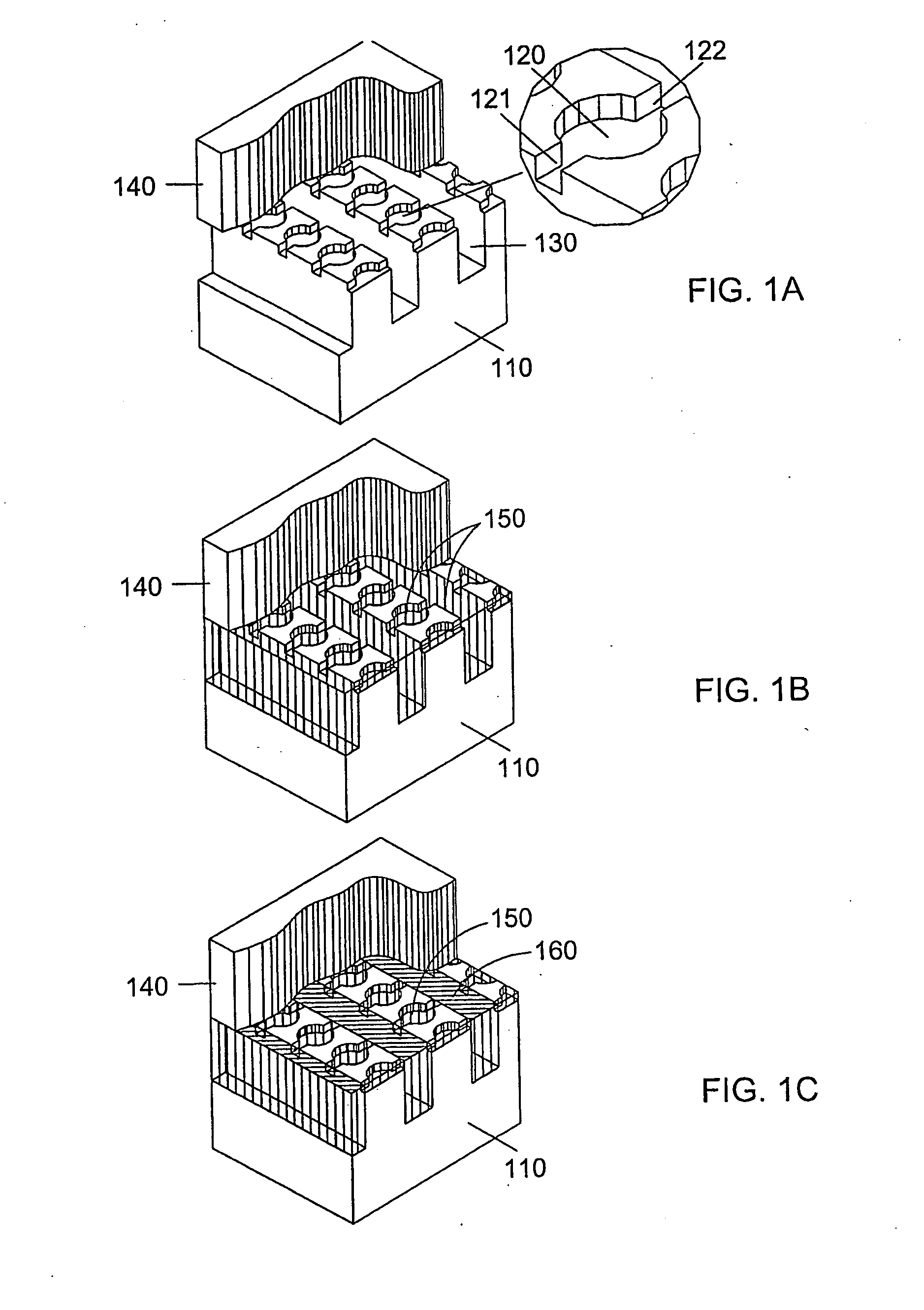
[0152]Another preferred variation of the present invention is the use of a microwell plate to perform hybridization-PCR assay. In a preferred embodiment a microwell plate contains a plurality of microwells of 1 to 500 microns in diameter and 1 to 500 microns deep. The plate can be made of glass, silicon, plastic, and any other appropriate materials. The fabrication of such a plate is well-know to those skilled in the art of microfabrication (Gao et al. U.S. Pat. No. 6,426,184). In a preferred embodiment, the microwell plate is assembled with an enclosure to form a fluidic device which contains inlet and outlet to allow fluids to be injected and / or circulated. An exemplary make and use of a glass-based microwell plates is described by Leproust et al. in “Digital light-directed synthesis. A microarray platform that permits rapid reaction optimization on a combinatorial basis”, J. Comb. Chem. 2, 349-354 (2000). For real-time PCR application, the bottom of the wells is covalently deposited with probe molecules containing primers and binding probes. In a preferred embodiment, the interior surface of the microwells is hydrophilic and the outside surface of the microwells hydrophobic. In an illustrative assay process, a solution containing DNA sample sequences is first circulated through the fluidic device at a proper temperature so that those sample sequences complimentary to respective binding probes would be hybridized and retained in the corresponding microwell while non-specific sample sequences would not be retained. A brief wash with a suitable buffer solution will then be applied to the fluidic device at a reduced temperature to wash the non-specific sample sequences out of the device while keeping the hybridized sample sequences in the microwells. A PCR mix based on SYBR Green I double-stranded DNA binding dye assay is then be injected into the device. As described in the above paragraphs, the PCR mix contains RNase A or other appropriate cleavage reagents. To avoid premature cleavage, chip temperature will be kept low (e.g. at 4° C.) when the PCR mix is injected into the device. An isolation fluid, such as oil or an inert gas, is then injected into the chip to isolate all the microwells and real-time PCR reaction is carried out thereafter.
[0153]Another alternative form of microwell plates is to facilitate a different isolation mechanism. Each microwell has an extruded lip. The microwells can be sealed or isolated by pressing an elastomer sheet or a laminate film having an adhesive coating against the microwells. The extruded lip helps the seal. The elastomer and the laminate film can be selected from various materials that are compatible with the temperatures used in PCR processes, chemically inert, and of low fluorescence.
[0154]Another aspect of the present invention is the use of beads within the fluidic device to significantly increase the synthesis capacity of the device for parallel synthesis applications. In a preferred embodiment the beads are made of high-loading substrate materials including but not limited to partially crosslinked and functionalized polystyrene beads, crosslinked polystyrene-PEG copolymer beads, CPG, and various other commonly used and specialized resin material used in solid phase synthesis. In a preferred embodiment, all beads are substantially spherical and of narrow size distribution. A fluidic device similar to that shown in FIG. 2A, except the structure of the reaction chambers, is used. In one aspect of the present invention the outlet side of each reaction chamber contains a barrier to stop beads from passing through and allow liquid to flow through. The bypass channels should be wide enough to allow beads to pass through so as to avoid plugging of the transport channels by the beads. Before loading the beads into the reaction chambers, the beads are suspended in a liquid having substantially the same density as that of the beads (excluding the void inside the beads). Then, the bead suspension liquid is circulated through the fluidic device till all the reaction chambers are filled with the beads. The process of using the bead-loaded fluidic device for chemical synthesis is similar to that of a regular device as what is described in the above paragraphs.
[0155]FIG. 10 schematically illustrates a bead-containing chip. For illustration purpose, only a 1D array is shown. A 2D array, which is the format of a real chip, can be constructed by repeating the 1D structure in the y direction. During an operation, the fluid enters the chip through a main inlet channel 1071, splits and flows into inlet transport channel 1030, further splits and flows through reaction chamber 1020, merges into outlet transport channel 1032, and further merges into a main outlet channel 1072 and flows out of the chip. A portion of the incoming fluid reaches the main outlet channel 1072 through inlet or outlet bypass channels 1031 and 1033 without passing through any reaction chambers 1020 or the inlet transport channel 1030. The function of the bypass channels 1031 and 1033 will be described later. The main considerations in the design of this chip include fluid flow distribution, synthesis capacity, bead-loading mechanism, chemical and photochemical reaction efficiency, device fabrication, and production cost.

Problems solved by technology

Traditional methods of making and examining the compounds one at a time are becoming increasingly inadequate.
In spite of the usefulness of the currently available DNA microarrays, their performance is far from being satisfactory for many applications.
Inadequate assay specificity is one of a multitude of limitations with the current DNA microarray methodology, which are fundamentally associated with the single-pair hybridization assay, i.e. with results determined by the hybridization of only one pair of nucleotide molecules.
Selection of hybridization probes is a complex issue, particularly for gene expression applications, in which samples contain tens of thousands genes.
Shorter oligo probes should theoretically provide higher hybridization discrimination but they tend to have poor hybridization properties leading to lower sensitivity, not to mention the difficulty of finding short unique sequences in large genomes (Shchepinov et al.
Today's DNA microarrays are not suitable for quantitative measurement.
This will likely become one of the roadblocks to hinder the technology from being used as a clinical diagnostic tool, although technological efforts have been made to address this problem (Dudley et al.
According to the published data, while about 70% of array results of highly differentiated genes were qualitatively consistent with real-time PCR, consistent validation was not achieved for genes showing less than a four-fold change on the array.
The third limitation of today's DNA microarray is detection sensitivity.
However, some of the clinical biopsy tissue samples yield less than 1 microgram of total RNA sample.
This method, however, causes concerns for altering ratios of the genes involved.
For example, if in one event a forward primer happened to prime to a wrong sample sequence and produced a wrong amplicon, this wrong amplicon will likely either not be recognized by the detection probe or not be further amplified by the reverse primer.
Moreover, the ability of real-time PCR to quantitatively measure the copy numbers of target sequences in samples is non-existent in today's DNA microarray technology.
However, its fluidic design and the operational principle fundamentally limit it from being able to achieve the degree of miniaturization and the level of area density that have demonstrated in DNA microarrays (U.S. Pat. No. 6,272,939).

Method used


Image

  • Fluidic devices and methods for multiplex chemical and biochemical reactions
  • Fluidic devices and methods for multiplex chemical and biochemical reactions
  • Fluidic devices and methods for multiplex chemical and biochemical reactions

Examples


example 1

Isolation of Chambers

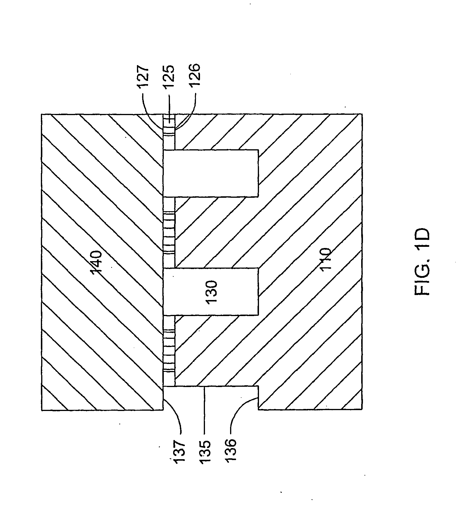
[0161]A microfluidic array device is fabricated using a 500-μm thick silicon wafer as a fluidic template and a 500-μm thick glass wafer as a cover plate. Fluidic structures are similar to that of FIG. 2A. The structures include 20×6=120 circular-shaped chambers of 100 μm diameter and 15 μm deep. The inlet and outlet conduits are 12 μm wide, 15 μm deep and 40 μm long. Seven tapered transport channels are 2,400 μm long, 150 μm deep, and have a taper width ramping down from 75 μm to 72 μm. Bypass channels are 39 μm wide, 150 μm deep and 310 μm long. The fluidic structures were formed using DRIE (Surface Technology Systems plc, Newport, UK) etched. The interior surfaces of the chambers are oxidation-formed silicon dioxide on the silicon substrate side and glass surface on the glass cover side. The interior surfaces of the channels of both silicon and glass sides were coated with perfluorocarbon monolayer formed by selective coating of the surfaces with 0.5% (heptade...

example 2

PCR using RNase A Cleaved Oligo Primers

[0163]PCR reactions were carried out using on a MJ Research PTC-225 Peltier Thermal Cycler and in 25 μL volumes. JumpStart Taq polymerase and a companion buffer solution (Sigma-Aldrich, St. Louis, Mo., USA) were used for the PCR reactions. In the buffer solution, 200 μM dNTP, 2.5 mM MgCl2 (divalent cation), and 0.05% BSA were added. A 78-mer oligo DNA of 1 pg, with the sequence showing in the following, was used as a template.

#4126AGCATAGGATCCGCGATGAGCGATCGCATGACAACGAGCTAAGTCCAGCGATCGCAGCTGGTTTTTTGAATTCATGCGT

[0164]A composite primer that contains two rU sites and a sequence showing in the following was used. The concentration used was 2 μM.

#4148GACCACGAGCATAGGATCCG(rU)CTCGTCCGACGCATGAATTC(rU)TTTTTTTTTT

[0165]The above components were added to all PCR tubes.

[0166]The temperature program was following: 94° C. for 60 sec, 35×(94° C. for 30 sec, 55° C. for 30 sec, 72° C. for 60 sec), 72° C. for 60 sec, hold at 4° C.

[0167]To RNase A cleavage and PCR ...


PUM

PropertyMeasurementUnit
distancesaaaaaaaaaa
distancesaaaaaaaaaa
distancesaaaaaaaaaa

Abstract

The present invention describes microfluidic devices that provide novel fluidic structures to facilitate the separation of fluids into isolated, pico-liter sized compartments for performing multiplexing chemical and biological reactions. Applications of the novel devices including biomolecule synthesis, polynucleotide amplification, and binding assays are also disclosed.

Description

[0001]This application claims the benefit of U.S. Provisional Application No. 60 / 545,435, filed on Feb. 18, 2004.STATEMENT REGARDING FEDERALLY SPONSORED RESEARCH OR DEVELOPMENT[0002]Not applicable.REFERENCE TO A “MICROFICHE APPENDIX”[0003]Not applicable.BACKGROUND OF THE INVENTION[0004]1. Field of the Invention[0005]The present invention relates to the field of fluidic devices for carrying out multiplex chemical or biochemical reactions and for performing multiplex chemical and / or biochemical assays. More particularly, this invention relates to devices and methods for distributing fluids into a plurality of compartments for carrying out multiplex chemical and / or biochemical reactions, and detecting a plurality of chemical and / or biochemical compounds.[0006]2. Description of Related Art[0007]Modern drug development, disease diagnosis, pathogen detection, gene discovery, and various genetic-related technologies and research increasingly rely on making, screening, and assaying a large ...

Claims


Application Information

Patent Timeline
Patent Type & Authority Applications(United States)
IPC IPC(8): C40B50/06C40B60/14C12P19/34B01L3/00B01L7/00C07H21/04C12M1/36C12Q1/68
CPCB01L3/5027B01L7/52B01L2200/0605B01L2300/0864B01L2300/161B01L2400/0406B01L2400/0688C12Q1/686C07H21/04C12Q2537/143C12Q2565/501C12Q2565/629
Inventor ZHOU, XIACHUANGULARI, ERDOGANGAO, XIAOLIAN
Owner LC SCI LC
Learn More