
Self-powered integrated hydraulic oil cylinder

A hydraulic cylinder and power technology, which is applied in the field of self-powered integrated hydraulic cylinder, can solve the problems of scattered configuration, many parts, large hydraulic system volume, etc., and achieve the reduction of hydraulic drive mechanism, less leakage points, and reduced land occupation The effect of area and volume

Pending Publication Date: 2020-12-01
南京市江宁区艾机机械厂
View PDF6 Cites 0 Cited by
  • Summary
  • Abstract
  • Description
  • Claims
  • Application Information

AI Technical Summary

Problems solved by technology

[0003] The purpose of the present invention is to design a self-powered integrated hydraulic cylinder with a small oil supply volume that does not require an oil pump to solve the problems of the existing hydraulic system with large volume, many parts and scattered configurations.

Method used


Image

  • Self-powered integrated hydraulic oil cylinder
  • Self-powered integrated hydraulic oil cylinder

Examples


Embodiment 1

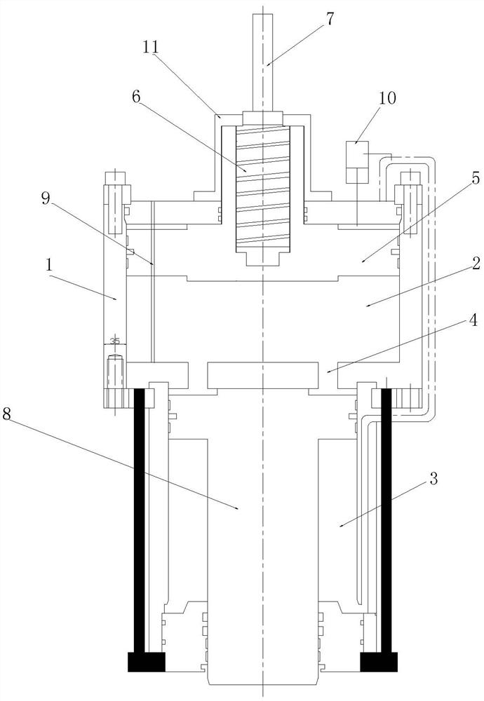
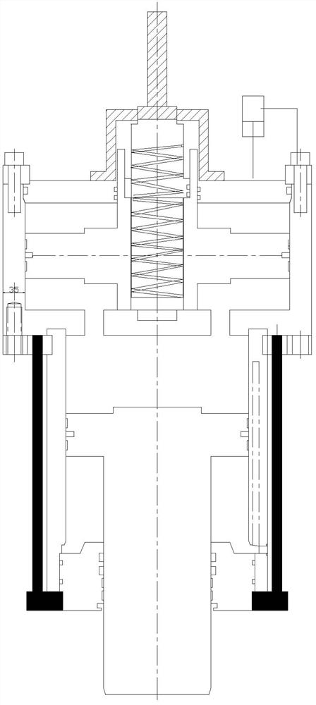
[0020] Such as figure 1 shown.

[0021] A self-powered integrated hydraulic oil cylinder, which includes a cylinder body 1, such as figure 1 As shown, the cylinder body is composed of a pressure generating chamber 2 filled with hydraulic oil and a power output chamber 3. The pressure generating chamber 2 and the power output chamber 3 are connected through a through hole 4. The pressure generating chamber 2 is installed There is a piston 5, which divides the pressure generating chamber into a high-pressure chamber and a low-pressure chamber. The center of the piston 5 is provided with a screw hole, and a screw 6 is installed in the screw hole. It is connected with the output shaft 7 of the servo motor (or other motors); in order to prevent the rotation of the piston 5 and reduce wear and tear, the piston 5 can realize its linear movement in the pressure generating chamber 2 by adding an anti-rotation mechanism during specific implementation. The grinding performance is good ...

Embodiment 2

[0024] The difference between this embodiment and Embodiment 1 is that the axis of the T-shaped piston rod 8 is installed eccentrically with the axis of the piston 5 .

Embodiment 3

[0026] The difference between this embodiment and Embodiment 1 is that the axis line of the T-shaped piston rod 8 is installed perpendicular to the axis of the piston 5. At this time, it is only necessary to connect a transition cylinder on the cylindrical surface of the pressure generating chamber 2, and pass through the transition cylinder. It is enough to realize the communication between the pressure generating chamber 2 and the power output chamber 3 .


PUM


Abstract

The invention discloses a self-powered integrated hydraulic oil cylinder. The self-powered integrated hydraulic oil cylinder comprises a cylinder body. The self-powered integrated hydraulic oil cylinder is characterized in that the cylinder body is composed of a pressure generating cavity filled with hydraulic oil and a power output cavity, the pressure generating cavity is communicated with the power output cavity through a through hole, a piston is installed in the pressure generating cavity and divides the pressure generating cavity into a high-pressure cavity and a low-pressure cavity, a screw hole is formed in the center of the piston, a screw rod is installed in the screw hole, and the screw rod is connected with an output shaft of a driving motor; the piston realizes linear movementin the pressure generating cavity through an anti-rotation mechanism; a T-shaped piston rod is installed in the power output cavity, the small end of the T-shaped piston rod stretches out of the cylinder body, the large end of the T-shaped piston rod divides the power output cavity into a rod cavity and a rodless cavity, the rodless cavity is communicated with the high-pressure cavity of the pressure generating cavity, and the rod cavity is communicated with the low-pressure cavity of the pressure generating cavity through an oil pipe or an oil way in the cylinder body. The self-powered integrated hydraulic oil cylinder is simple in structure, small in size, free of leakage and small in working temperature rise.

Description

technical field [0001] The invention relates to a hydraulic technology, in particular to a hydraulic oil cylinder, in particular to a self-powered integrated hydraulic oil cylinder. Background technique [0002] At present, in order to ensure the normal operation of the hydraulic cylinder, the oil pump is usually required to provide pressure oil, and then the pressure oil is sent to the oil inlet of the cylinder through various pipelines and valves to drive the piston rod. This method has been used for decades, and its maximum The biggest problem is that there is oil leakage, the structure is complex, the volume is large, and the temperature rises quickly, especially the scattered layout of each part, which affects the miniaturization of the equipment, and is a fatal flaw for the vehicle equipment. Therefore, how to install the hydraulic cylinder Integration, miniaturization, intelligence, and high pressure are problems to be solved in the field of hydraulic research. Cont...

Claims


Application Information

Patent Timeline
Patent Type & Authority Applications(China)
IPC IPC(8): F15B15/14F15B15/20
CPCF15B15/1423F15B15/20
Inventor 王翀王国云
Owner 南京市江宁区艾机机械厂
Learn More